
TM 1-4920-436-13&P
FIELD MAINTENANCE
ENGINE SHOP
MAINTENANCE INSTRUCTIONS FOR DOOR LOCK TABS
INITIAL SETUP:
Materials/Parts (cont.)
Tools and Special Tools
Disc Grinder (WP 0060 00, Table 2, Item 101 )
Rag, Wiping (WP 0066 00, Item 7)
Drill Set, Twist (WP 0060 00, Table 2, Item 102 )
Tan 686 (WP 0066 00, Item 8)
General Mechanics Tool Kit
Personnel Required
(WP 0060 00, Table 2, Item 104 )
CMF 44-B Metal Worker (1)
Hand Yoke Riveter (WP 0060 00, Table 2, Item 105 )
References
Paint Brush (WP 0060 00, Table 2, Item 107 )
TM 1-1500-204-23
Portable Electric Drill (WP 0060 00, Table 2, Item 108 )
TM 43-0139
Materials/Parts
Equipment Condition
Polysulide Sealant (WP 0066 00, Item 5)
Primer, Coating (WP 0066 00, Item 6)
Functional
INSPECTION OF INSTALLED ITEMS
DOOR LOCK TABS
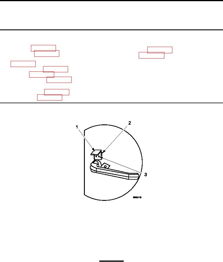
Figure 1.
Door Lock Tabs.
1.
Inspect door lock tabs (Figure 1, Item 1) for broken or cracked welds (Figure 1, Item 2).
2.
Ensure rivets (Figure 1, Item 3) are secure.
3.
Replace door lock tabs (Figure 1, Item 1) if damage is detected.
REMOVAL
DOOR LOCK TABS
CAUTION
Use extreme care not to grind or cut through the shelter skin.
1.
Grind welds (Figure 1, Item 2) from damaged door lock tabs (Figure 1, Item 1).
2.
Drill out two rivets (Figure 1, Item 3) attaching door lock tabs (Figure 1, Item 1).
0049 00-1