
TM 1-4920-436-13&P
FIELD MAINTENANCE
ENGINE SHOP
MAINTENANCE INSTRUCTIONS FOR WATER AND AIR FEED-THRU CONNECTOR ASSEMBLIES
INITIAL SETUP:
Personnel Required
Tools and Special Tools
CMF 15 Series (2)
General Mechanics Tool Kit
(WP 0060 00, Table 2, Item 104 )
Equipment Condition
Materials/Parts
Functional
Compound, Caulking (WP 0066 00, Item 1)
INSPECTION OF INSTALLED ITEMS
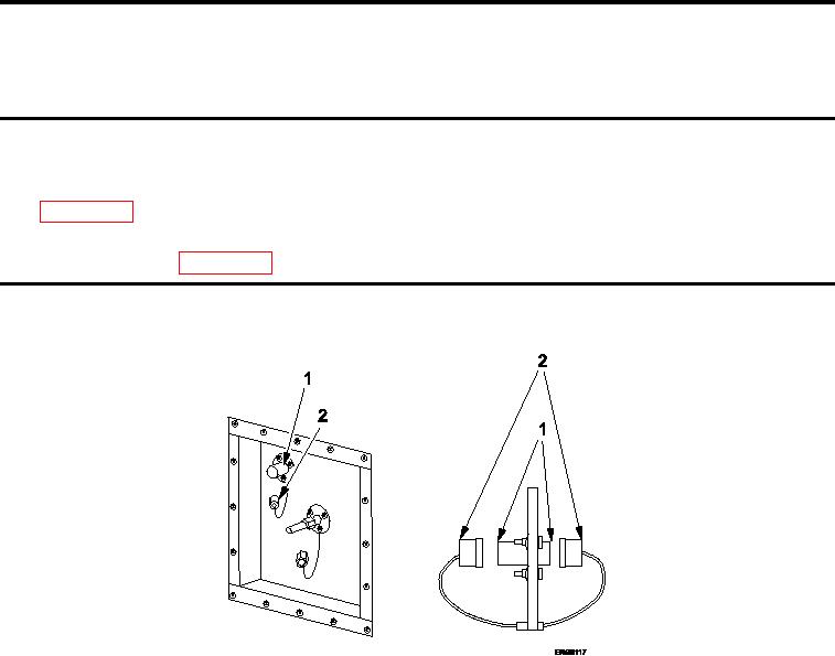
WATER FEED-THRU CONNECTOR ASSEMBLY
Figure 1.
Inspect Water Feed-Thru Connector Assembly.
1.
Inspect condition of threads on both ends of water feed-thru connector (Figure 1, Item 2).
2.
Replace if damage is detected.
3.
Ensure that protective dust caps (Figure 1, Item 1) are attached.
4.
Ensure that weld on connector is not cracked or broken. If defective, replace.
0050 00-1