
TM 1-4920-438-13&P
OPERATOR INSTRUCTIONS
POWER TRAIN SHOP
CONNECTING POWER TO THE SHELTER
INITIAL SETUP:
References
Tools and Special Tools
Electrical Repairers Tool Kit
(WP 0067 00, Table 2, Item 103 )
TM 9-6150-226-13
General Mechanics Tool Kit
TM 9-6150-226-23P
(WP 0067 00, Table 2, Item 104 )
Equipment Condition
Personnel Required
Functional
CMF 15 Series (2)
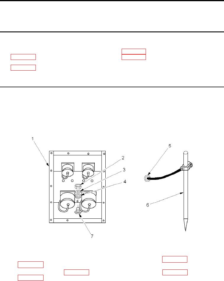
EXTERNAL GROUNDING OF SHELTER
NOTE
Shelter is grounded through an externally connected power supply. Consult a qualiied electri-
cian for proper grounding procedures required for surrounding soil conditions.
Figure 1.
External Grounding of Shelter.
1.
Remove ground rod assembly (Figure 1, Item 5 and 6) from shelter BII box (WP 0002 00, Figure 2, Item 8 or
WP 0002 00, Figure 3, Item 8).
2.
Remove slide hammer (WP 0072 00, Figure 2, Item 4) from Shelter BII box (WP 0002 00, Figure 2, Item 8 or
WP 0002 00, Figure 3, Item 8).
0006 00-1