
0032 00
TM 1-4920-438-13&P
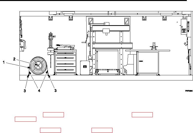
DISCONNECTING MAIN POWER CABLE - CONTINUED
Figure 4.
Securing Cable Reel Assembly.
11. Remove two setscrews from loor inserts at 60 amp power cable reel assembly transport location.
12. Store setscrews (WP 0072 00, Figure 2, Item 18 or 19) in shelter BII box (WP 0002 00, Figure 2, Item 8 or
WP 0002 00, Figure 3, Item 8).
13. Remove cargo strap (Figure 4, Item 4) from secure storage location and two ring bolts (Figure 4, Item 3) from
shelter BII box (WP 0002 00, Figure 2, Item 8 or WP 0002 00, Figure 3, Item 8).
14. Insert ring bolts (Figure 4, Item 3) into loor inserts at transport location.
15. Position 60 amp power cable reel assembly at transport location.
16. Secure 60 amp power cable reel assembly to ring bolts (Figure 4, Item 3) with cargo strap (Figure 4, Item 4).
0032 00-4