
0059 00
TM 1-4920-438-13&P
INSTALLATION CONTINUED
NON-METALLIC HOSE AND FITTINGS CONTINUED
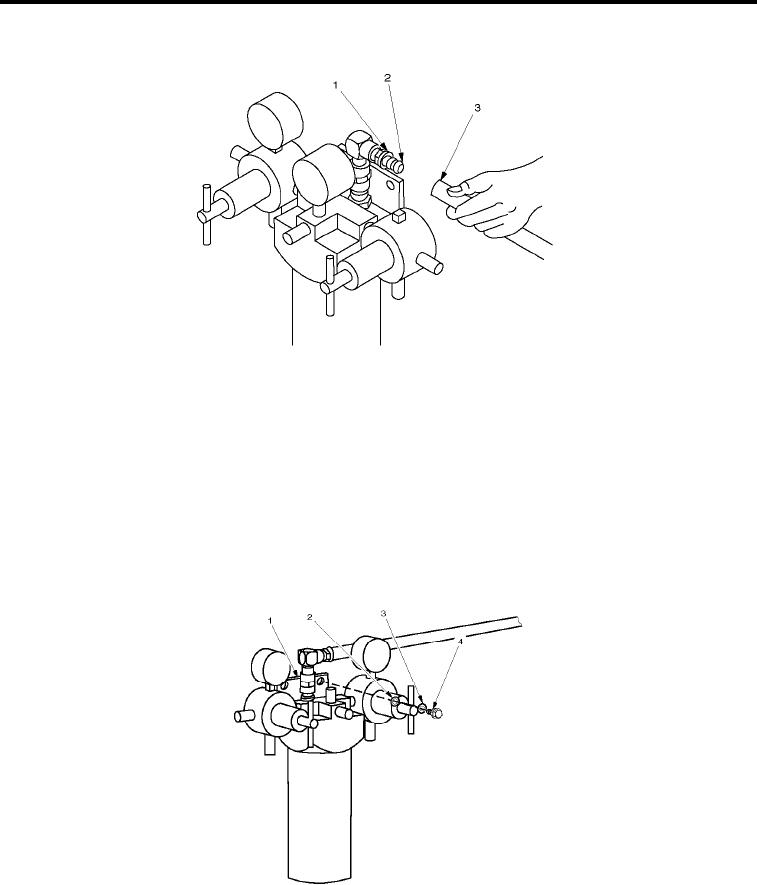
Figure 6.
Hose Reinstallation.
2.
Push non-metallic hose (Figure 6, Item 3) on itting (Figure 6, Item 2) until end seats against protective cap
(Figure 6, Item 1).
3.
Reinstall loop clamps (Figure 2, Item 1) with bolts (Figure 2, Item 2) in original position and secure.
INSPECTION OF INSTALLED ITEMS
OIL AND WATER SEPARATOR
NOTE
Remove center gauge if necessary to tighten bolts.
Figure 7.
Inspect Oil/Water Separator.
1.
Inspect oil/water separator hardware (Figure 7, Item 2 through Figure 7, Item 4) for rust, cracks and rounded
heads.
0059 00-4