
TM 1-4920-438-13&P
FIELD MAINTENANCE
POWER TRAIN SHOP
MAINTENANCE INSTRUCTIONS FOR ECU SECURITY SCREENS
INITIAL SETUP:
Personnel Required
Tools and Special Tools
CMF 15 Series (1)
General Mechanics Tool Kit
(WP 0067 00, Table 2, Item 104 )
References
Torque Wrench, 0-600 in. lbs
TM 1-1500-204-23
(WP 0067 00, Table 2, Item 109 )
Equipment Condition
Functional
INSPECTION OF INSTALLED ITEMS
ECU SECURITY SCREENS
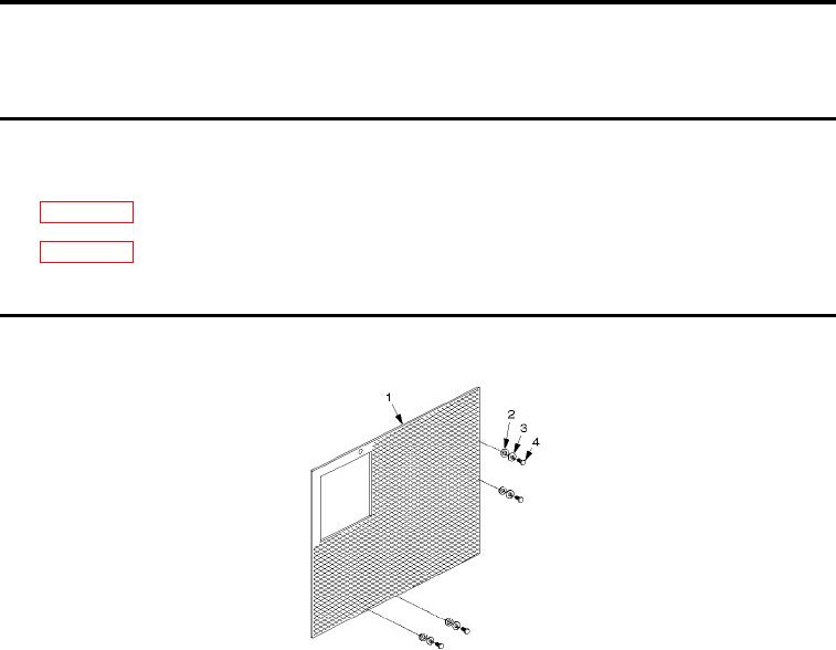
Figure 1.
ECU Security Screen.
1.
Inspect ECU security screen (Figure 1, Item 1) for damage. Replace as necessary.
2.
Inspect ECU security screen hardware (Figure 1, Item 2 through 4) for rust, cracks, and rounded heads.
Replace as necessary.
REMOVAL
ECU SECURITY SCREENS
1.
Remove four bolts (Figure 1, Item 4), four lock washers (Figure 1, Item 3), and four lat washers (Figure 1,
Item 2).
2.
Inspect bolts (Figure 1, Item 4) for thread damage.
3.
Replace bolts (Figure 1, Item 4) if damage is detected.
0061 00-1