
TM 1-4920-440-13&P
0007 00
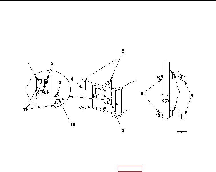
INSTALLING AREA LIGHT
NOTE
Do not remove area light wing nuts from screws.
When area light is installed at cargo end of shelter, cable is routed over top of shelter.
Excess cable slack should be neatly coiled on area light post so that it does not present a
hazard to personnel.
Figure 5.
Installing Area Light.
1.
Remove area light (Figure 5, Item 5) from inside ixed personnel end wall (Figure 5, Item 4) by loosening, NOT
removing, two wing nuts (Figure 5, Item 6) and sliding mounting screws (Figure 5, Item 7) out of mounting
brackets (Figure 5, Item 8).
2.
Remove bulb from shelter Basic Issue Items (BII) box (WP 0002 00, Figure 2, Item 5 or Figure 3, Item 6) and
twist into light socket.
3.
Unroll area light cable (Figure 5, Item 10).
4.
Install area light (Figure 5, Item 5) on outside of ixed personnel (Figure 5, Item 4) or cargo end wall by sliding
mounting screws (Figure 5, Item 7) on area light (Figure 5, Item 8).
5.
Secure area light (Figure 5, Item 5) to mounting brackets (Figure 5, Item 8) by tightening two wing nuts
(Figure 5, Item 6) on area light (Figure 5, Item 5).
6.
Remove protective dust cap (Figure 5, Item 11) from either "J3" or "J4" connector (Figure 5, Item 1 or 2) on
power entry panel (Figure 5, Item 9).
7.
Remove protective dust cap (Figure 5, Item 11) from area light cable (Figure 5, Item 10).
8.
Connect area light cable (Figure 5, Item 10) into "J3" or J"4" connector (Figure 5, Item 1 or 2) on power entry
panel (Figure 5, Item 9) and secure with lock ring (Figure 5, Item 3).
END OF WORK PACKAGE
0007 00-5/6 blank