
TM 1-4920-440-13&P
0034 00
RAISING HINGED FLOOR - CONTINUED
1.
Remove lockout pins (Figure 7, Item 4) from lower position on both load balancers (Figure 7, Item 3).
2.
Open slide stops (Figure 7, Item 1) against support cables (Figure 7, Item 2) on both load balancers (Figure
7, Item 3).
3.
Replace lockout pins (Figure 7, Item 4) in upper position on both load balancers (Figure 7, Item 3).
WARNING
Expandable sections, which consist of hinged loor and hinged sidewall, weighs 700 lbs (318
kg). DO NOT stand directly in front of hinged section. Standing directly in front of hinged section
could cause SERIOUS INJURY to personnel.
NOTE
If hinged loor and corner post bind, re-level shelter.
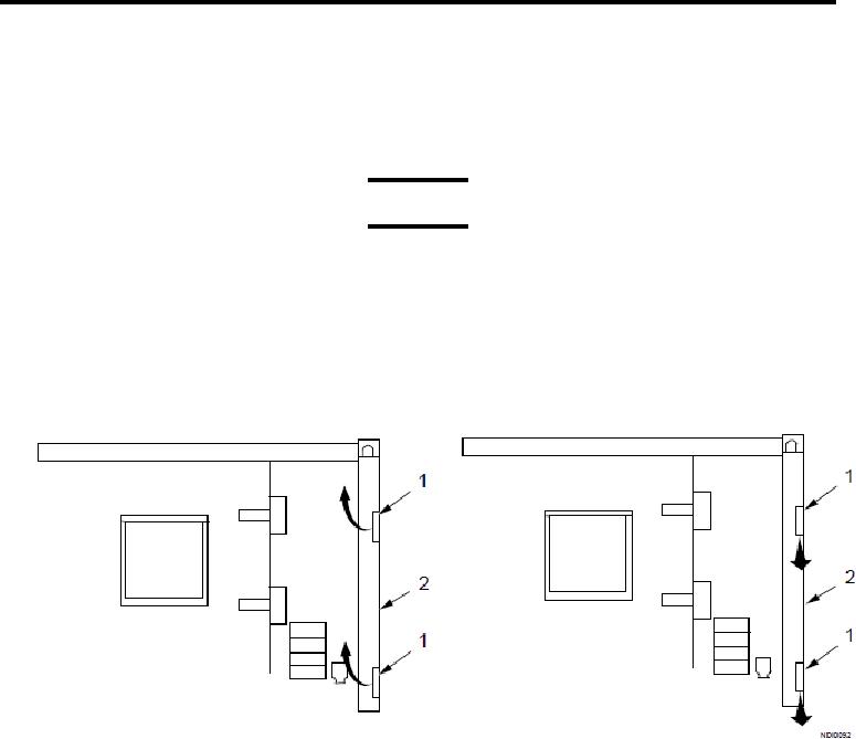
Figure 8.
Cam Lock Handles.
4.
Position cam locks so handles are vertical and down for cargo end and vertical and up on personnel end of
shop.
5.
Raise hinged loor and secure to corner post (Figure 8, Item 2) with cam lock handles (Figure 8, Item 1).
6.
Rotate cam lock handles (Figure 8, Item 1) as indicated and engage lower locks irst. Ensure that pins are in
holes.
0034 00-7