
0034 00
TM 1-4920-440-13&P
RELEASING SHELTER WALLS
Figure 1.
Releasing Shelter Walls.
1.
Lower two support strut assemblies (Figure 1, Item 2) from hinged roof by removing pin (Figure 1, Item 1).
2.
Extend support strut assemblies (Figure 1, Item 2) to their full length and insert pin (Figure 1, Item 1).
3.
Using two personnel, raise roof with support strut assemblies (Figure 1, Item 2) and set support strut assem-
blies (Figure 1, Item 2) in place.
CAUTION
Ensure hinged end wall do not hit Velcro straps to prevent damage.
NOTE
Stencil on jack indicates handle rotation to raise or lower jack.
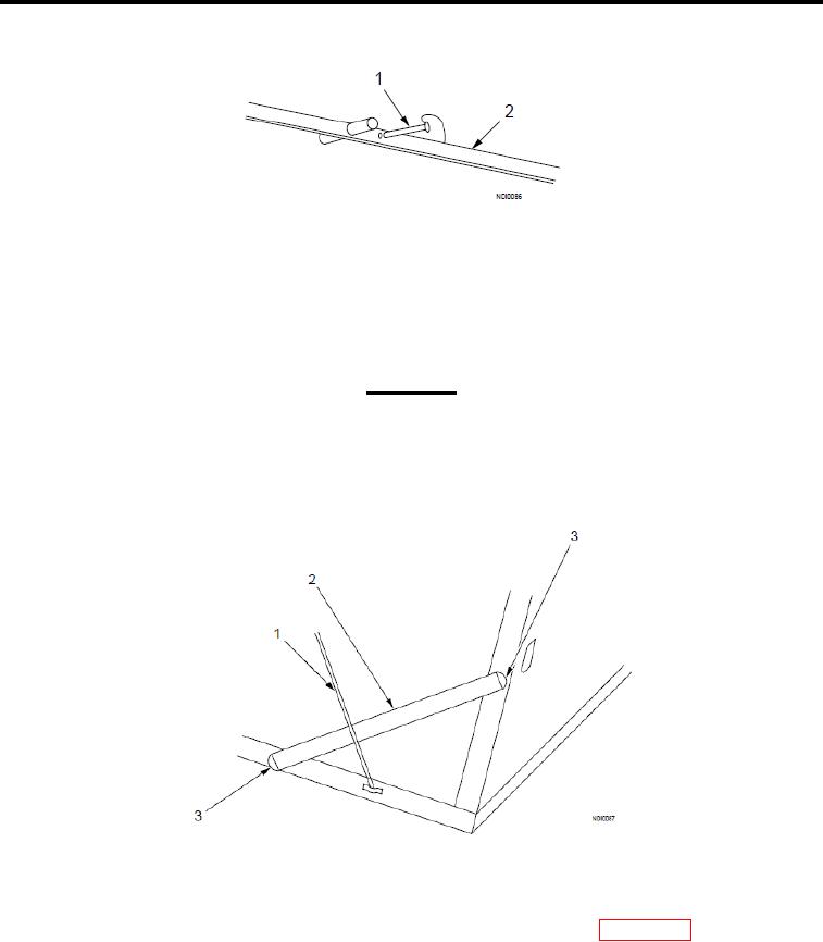
Figure 2.
Removing Sidewall Support Braces.
4.
Simultaneously lower hinged loor with hinged jacks until hinged end walls can swing freely.
5.
Remove two sidewall support braces (Figure 2, Item 2) from shelter BII box (WP 0002 00, Figure 2, Item 5 or
Figure 3, Item 6).
6.
Install two sidewall support braces (Figure 2, Item 2) in brace cups marked "A" (Figure 2, Item 3) on hinged
loor and sidewall behind support cable (Figure 2, Item 1).
7.
Place two ECU cables over each hinged end wall and secure cable ends to ECU screen.
8.
Fold in each hinged end wall to roof beam and hold in place with Velcro straps.
0034 00-2