
0048 00
TM 1-4920-440-13&P
WARNING
HIGH VOLTAGE exists in electrical system of shop. All electrical inspections, repairs, or
replacements will be performed with power OFF and only by a qualiied electrician. Serious
shock hazards exist which could result in INJURY OR EVEN DEATH to personnel.
NOTE
During installation of components, same hardware should be used so as to maintain original
integrity of shop set.
INSPECTION OF INSTALLED ITEMS
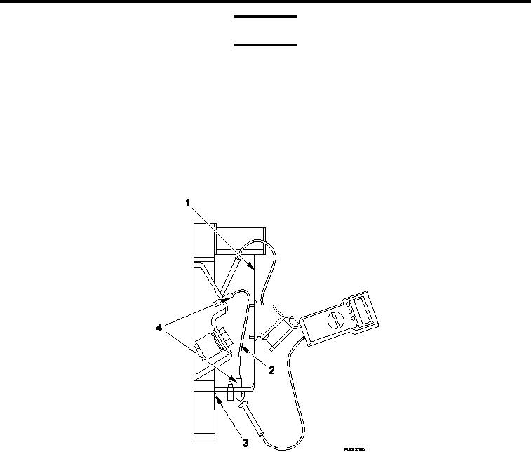
Figure 1.
BNC Connector Assembly.
1.
Move main circuit breaker to OFF position.
2.
Remove four screws (Figure 1, Item 3) attaching power entry panel cover (Figure 1, Item 1) which is located
below circuit breaker panel.
3.
Remove power entry panel cover (Figure 1, Item 1) from power entry panel.
4.
Visually inspect BNC connectors (Figure 1, Item 4) and cable (Figure 1, Item 2) for damage.
5.
Move main circuit breaker to ON position.
TEST AND INSPECTION
1.
Move main circuit breaker to OFF position.
2.
Remove four screws (Figure 1, Item 3) attaching power entry panel cover (Figure 1, Item 1) which is located
below circuit breaker panel.
3.
Remove power entry panel cover (Figure 1, Item 1) from power entry panel.
4.
Test BNC connector (Figure 1, Item 4) for continuity.
0048 00-2