
TM 1-4920-440-13&P
0048 00
TEST AND INSPECTION CONTINUED
5.
Replace BNC connector (Figure 1, Item 4) if breakage is detected.
6.
Move main circuit breaker to ON position.
REMOVAL
WARNING
HIGH VOLTAGE exists in electrical system of shop. All electrical inspections, repairs, or
replacements will be performed with power OFF and only by a qualiied electrician. Serious
shock hazards exist which could result in INJURY OR EVEN DEATH to personnel.
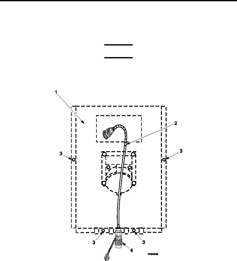
Figure 2.
Replace BNC Connector Assembly.
1.
Move main circuit breaker to OFF position.
2.
Remove four screws (Figure 2, Item 3) attaching power entry panel cover (Figure 2, Item 1) which is located
below circuit breaker panel.
3.
Remove power entry panel cover (Figure 2, Item 1) from power entry panel.
0048 00-3