
TM 1-4920-441-13&P
OPERATOR INSTRUCTIONS
TOOL CRIB SHOP
CONNECTING POWER TO THE SHELTER
INITIAL SETUP:
Tools and Special Tools
References
Electrical Repairers Tool Kit
TM 9-6150-226-13
(WP 0059 00, Table 2, Item 103 )
TM 9-6150-226-23P
General Mechanics Tool Kit
(WP 0059 00, Table 2, Item 104 )
Personnel Required
Equipment Condition
CMF 15 Series (2)
Functional
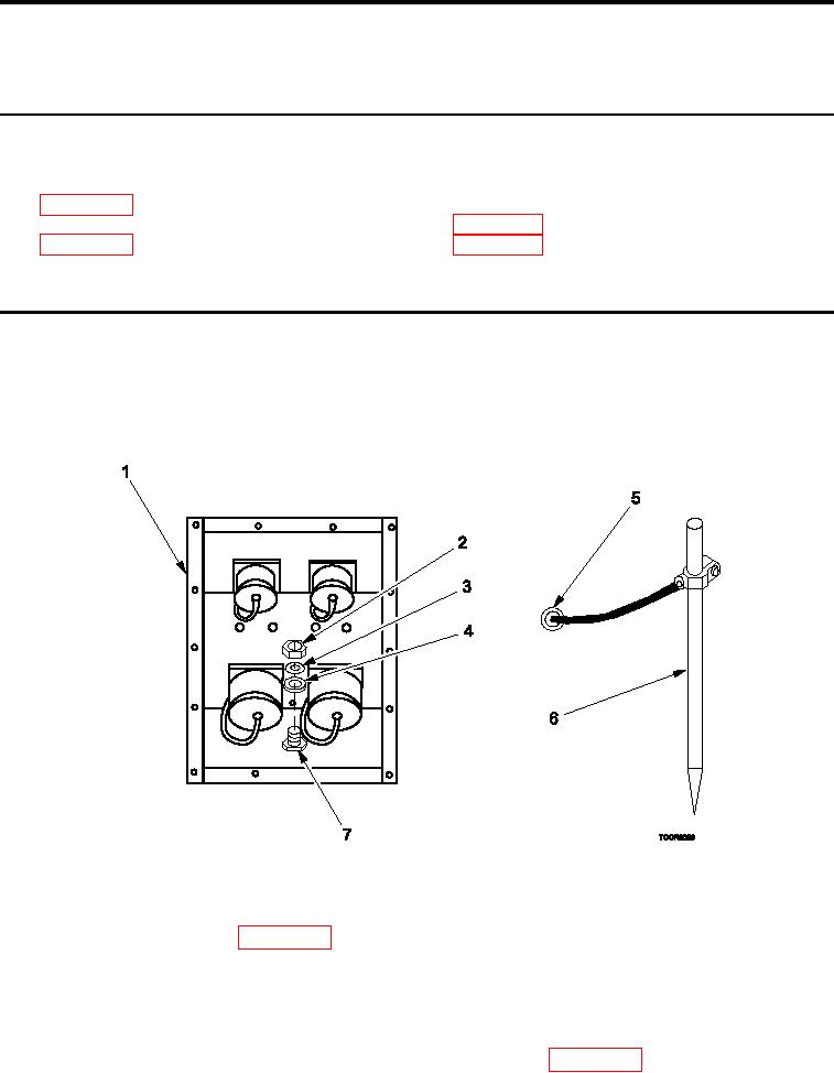
EXTERNAL GROUNDING OF SHELTER
NOTE
Shelter is grounded through an externally connected power supply. Consult a qualiied electri-
cian for proper grounding procedures required for surrounding soil conditions.
Figure 1.
External Grounding of Shelter.
1.
Remove ground rod assembly (Figure 1, Item 5 and 6) from shelter BII box .
2.
Remove slide hammer (WP 0064 00, Figure 2, Item 4) from shelter BII box .
NOTE
Ground rod location should permit ground cable lug to reach ground stud on power entry panel.
3.
Drive ground rod (Figure 1, Item 6) into ground using slide hammer (WP 0064 00, Figure 2, Item 4).
0006 00-1