
0046 00
TM 1-4920-441-13&P
WARNING
HIGH VOLTAGE exists in electrical system of shop. All electrical inspections, repairs, or
replacements will be performed with power OFF and only by a qualiied electrician. Serious
shock hazards exist which could result in INJURY OR EVEN DEATH to personnel.
NOTE
During installation of components same hardware should be used so as to maintain
original integrity of shop set.
If ECU NSN 4120-01-523-4472 is being used, it may be necessary to change existing
electrical plug connector on end of ECU cables to electrical plug connector (NSN 5935-
01-413-4953) to ensure ECU power cable is compatible with ECU.
INSPECTION OF INSTALLED ITEMS
ECU POWER CABLE
Inspect ECU power cable connectors and ECU power cable for any type of damage.
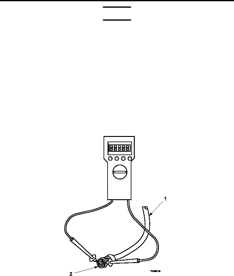
TEST AND INSPECTION
ECU POWER CABLE
Figure 1.
Testing ECU Power Cable.
1.
Move main circuit breaker to OFF position.
0046 00-2