
0046 00
TM 1-4920-441-13&P
REPAIR OR REPLACEMENT CONTINUED
ECU POWER CABLE CONTINUED
9.
Replace circuit breaker panel board and cover onto circuit breaker box.
10. Move main circuit breaker to the ON position.
TEST AND INSPECTION
BOX CONNECTOR FOR ECU POWER CABLE
WARNING
HIGH VOLTAGE exists in electrical system of shop. All electrical inspections, repairs, or
replacements will be performed with power OFF and only by a qualiied electrician. Serious
shock hazards exist which could result in INJURY OR EVEN DEATH to personnel.
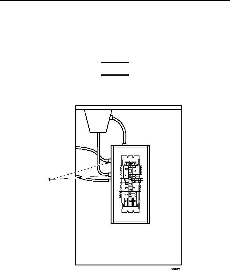
Figure 4.
Box Connector.
Inspect ECU box connector (Figure 4, Item 1) for damage. Replace as necessary.
0046 00-6