
TM 1-4920-441-13&P
0046 00
INSPECTION OF INSTALLED ITEMS
ELECTRICAL PLUG CONNECTOR
NOTE
If ECU NSN 4120-01-523-4472 is being used, it may be necessary to change existing electrical
plug connector on end of ECU cables to electrical plug connector (NSN 5935-01-413-4953) to
ensure ECU power cable is compatible with ECU.
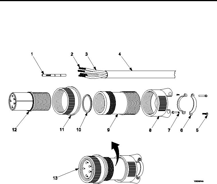
Figure 6.
Electrical Plug Connector.
Inspect electrical plug connector (Figure 6, Item 13) for damage that prevents safe operation. Replace as nec-
essary.
REMOVAL
ELECTRICAL PLUG CONNECTOR
Cut through power cable (Figure 6, Item 4) behind back shell (Figure 6, Item 8), removing electrical plug connec-
tor (Figure 6, Item 13).
INSTALLATION
ELECTRICAL PLUG CONNECTOR
1.
Strip 1.5 inch of outer insulation from power cable (Figure 6, Item 4).
2.
Strip .5 inch of outer insulation (Figure 6, Item 3) from ive wires (Figure 6, Item 2) contained within power
cable (Figure 6, Item 4).
3.
Install back shell (Figure 6, Item 8) onto power cable (Figure 6, Item 4).
0046 00-9