
TM 1-4920-441-13&P
0046 00
REPAIR OR REPLACEMENT CONTINUED
ECU POWER CABLE CONTINUED
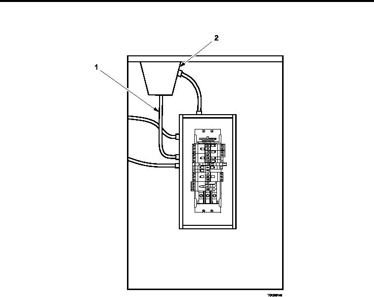
Figure 3.
Replacing ECU Power Cable.
3.
At electrical connector end of ECU power cable (Figure 3, Item 1), pull ECU power cable (Figure 3, Item
1) through ixed roof beam (Figure 3, Item 2). When ECU power cable (Figure 3, Item 1) has been pulled
completely out of ixed roof beam (Figure 3, Item 2), there should be an adequate amount of twine/rope left
at circuit breaker box end to allow for pulling rope back through with new ECU power cable (Figure 3, Item 1)
attached.
4.
After old ECU power cable (Figure 3, Item 1) has been pulled through, remove twine/rope and attach to new
ECU power cable (Figure 3, Item 1).
5.
At circuit breaker box end, pull twine/rope through ixed roof beam (Figure 3, Item 2) until correct amount of
ECU power cable (Figure 3, Item 1) is extending beyond end of ixed roof beam (Figure 3, Item 2). (A second
person at cargo door end guiding and feeding cable into ixed roof beam (Figure 3, Item 2) will make this
procedure easier).
6.
Remove twine/rope.
7.
Pull ECU power cable (Figure 3, Item 1) through box connector and tighten compression nut after ECU power
cable (Figure 3, Item 1) has been positioned with length (approximately 36 inches) of wire.
8.
Attach ECU power cable (Figure 3, Item 1) wires to circuit breaker with neutral and ground wires to corre-
sponding terminal strip.
0046 00-5