
TM 1-4920-500-13&P
0034 00
5
2
4
SSAE160
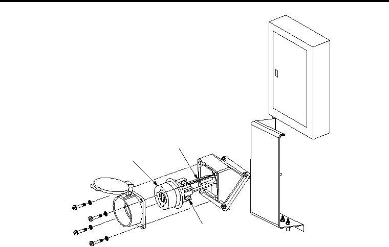
NOTE
Receptacle lugs are identified by letters "X", "Y", and "Z" with ground connection
being identified by color green. Black wire will be attached to "X", red wire will be
attached to "Y", and blue wire will be attached to "Z".
4. Loosen all lugs (4) on 60 AMP receptacle (1) and remove wires (5).
5. Remove four machine screws (6) from power entry panel cover (7).
6. Remove four nuts (8), four lock washers (9) and four bolts (10), which attach 54 degree angle adapter (3) to
power entry panel cover (7).
NOTE
Hardware for 54 degree angle 60 AMP receptacle is provided by manufacturer.
7. Install new 54 degree angle adapter (3) by installing four bolts (10), four lock washers (9) and four nuts (8) to
attach 54 degree angle adapter (3) to power entry panel cover (7).
8. Install four machine screws (6) on power entry panel cover (7).
NOTE
Receptacle lugs are identified by letters "X", "Y", and "Z" with ground connection
being identified by color green. Black wire will be attached to "X", red wire will be
attached to "Y", and blue wire will be attached to "Z".
9. Replace wires and tighten all lugs on 60 AMP receptacle.
10. Install four machine screws to attach 60 AMP receptacle to 54 degree adapter housing.
11. Move main circuit breaker to ON position.
0034 00-4