0011
TM 1-4920-924-13&P
AVIATION SHOP EQUIPMENT CONTACT MAINTENANCE (AV SECM) SYSTEM MAINTENANCE
INSTRUCTIONS FOR CURBSIDE ASSEMBLY - (CONTINUED)
1.
Install six aluminum rails (Figure 10, Item 8, 13, 15, 20, 23 and 28) onto six corner castings (Figure 10, Item
10, 14, 18, 21, 22 and 26).
2.
Install two corner castings (Figure 10, Item 29 and 31) into aluminum rail (Figure 10, Item 30).
3.
Install two corner castings (Figure 10, Item 4 and 19) into aluminum rail (Figure 10, Item 16).
4.
Install two corner castings (Figure 10, Item 29 and 31) into aluminum rails (Figure 10, Item 3 and 24).
5.
Install two corner castings (Figure 10, Item 4 and 19) into aluminum rails (Figure 10, Item 3 and 24).
6.
Install two corner castings (Figure 10, Item 4 and 19) into aluminum rails (Figure 10, Item 6 and 17).
7.
Install two corner castings (Figure 10, Item 7 and 12) into aluminum rail (Figure 10, Item 11).
8.
Install two corner castings (Figure 10, Item 7 and 12) into aluminum rails (Figure 10, Item 6 and 17).
9.
Install six corner castings (Figure 10, Item 4, 7, 12, 19, 29 and 31) into six aluminum rails (Figure 10, Item 8,
13, 15, 20, 23 and 28).
10.
Install twenty-eight 10-32 X 0.63 inch countersunk screws (Figure 10, Item 1), twenty-eight speed nuts
(Figure 10, Item 25), and seven large gussets (Figure 10, Item 27).
11.
Install twenty-four 10-32 X 0.63 inch countersunk screws (Figure 10, Item 1), twenty-four speed nuts
(Figure 10, Item 25), and twelve small gussets (Figure 10, Item 9).
12.
Install two support plates (Figure 10, Item 2 and 5).
13.
Install sixty-four 10-32 X 0.63 inch countersunk screws (Figure 10, Item 1) and sixty-four speed nuts
(Figure 10, Item 25) to secure support plates (Figure 10, Item 2 and 5).
END OF TASK
INSTALL HELICAL
2
1
3
1
3
3
1
3
SECM0016
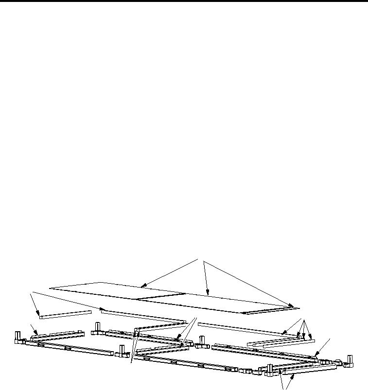
Figure 11. Curbside Assembly First Shelf
1.
Place shims (Figure 11, Item 1) on aluminum rails (Figure 11, Item 3).
2.
Place support plates (Figure 11, Item 2) on shims (Figure 11, Item 1) and ensure holes in shims
(Figure 11, Item 1) and support plates (Figure 11, Item 2) are properly aligned.
3.
Match drill holes of support plates (Figure 11, Item 2) and shims (Figure 11, Item 1) to 13/64 inch through
aluminum rails (Figure 11, Item 3).
4.
Remove support plates (Figure 11, Item 2) and shims (Figure 11, Item 1).
001114

