
0011
TM 1-4920-924-13&P
AVIATION SHOP EQUIPMENT CONTACT MAINTENANCE (AV SECM) SYSTEM MAINTENANCE
INSTRUCTIONS FOR CURBSIDE ASSEMBLY - (CONTINUED)
Third Shelf
1
2
FLUIDLINE
FUEL CELL
FUEL CELL
ELECTRICAL
HEAT GUN
BORESCOPE
SKIN REPAIR
SKIN REPAIR
KIT
4
3
7
6
4
8
5
9
SECM0018
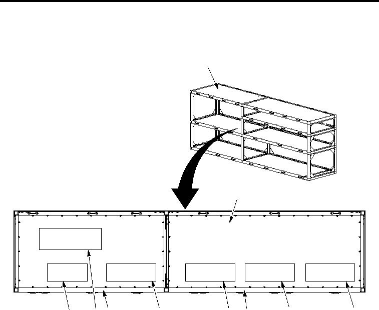
Figure 14. Third Shelf Stencil Application
1.
On SECM curbside assembly (Figure 14, Item 1) third shelf (Figure 14, Item 2), measure 2.00 inches
from front edge of aluminum rail (Figure 14, Item 7) for stencil placement for Heat Gun (1025209-23)
(Figure 14, Item 9).
2.
Measure 12.88 inches from front edge of aluminum rail (Figure 14, Item 7) for stencil placement for Fluidline
Low Pressure (1025209-19) (Figure 14, Item 8).
3.
Measure 2.00 inches from front edge of aluminum rail (Figure 14, Item 7) for stencil placement for Electrical
Kit (1025209-27) (Figure 14, Item 6).
4.
Measure 2.00 inches from front edge of aluminum rail (Figure 14, Item 5) for stencil placement for Fuel
Cell Skin Repair (1025209-17) (Figure 14, Item 4).
5.
Measure 2.00 inches from front edge of aluminum rail (Figure 14, Item 5) for stencil placement for Borescope
(1025209-15) (Figure 14, Item 3).
001118