
0012
TM 1-4920-924-13&P
AVIATION SHOP EQUIPMENT CONTACT MAINTENANCE (AV SECM) SYSTEM MAINTENANCE
INSTRUCTIONS FOR ROADSIDE RACK ASSEMBLY - (CONTINUED)
REMOVE
1
2
3
8
7
6
5
4
SECM0022
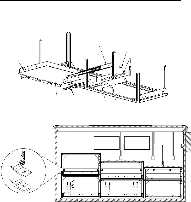
Figure 2.
Roadside Rack Assembly Removal (Sheet 1 of 2).
9
10
11
12
13
14
10
11
SECM0023
Figure 2.
Roadside Rack Assembly Removal (Sheet 2 of 2).
1.
From bottom of SECM roadside rack assembly, remove sixteen 1/4-20 X 0.50 inch low head screws
(Figure 2, Item 6), sixteen self clinching nuts (Figure 2, Item 8) and two shelf assemblies (Figure 2, Item 7).
2.
Remove eight 1/4-20 X 0.63 inch low head screws (Figure 2, Item 2), eight self clinching nuts (Figure 2, Item
8), and two drawer slides (Figure 2, Item 1) from center of roadside rack assembly.
00123