TM 10-5411-236-13&P
OPERATOR'S, UNIT, AND DIRECT SUPPORT MAINTENANCE
AUTHORIZED STOCKAGE LIST MOBILITY SYSTEM (ASLMS)
MODEL NUMBER FPU-8/12 PARTS (OD) P/N 15005002-001
NSN 5411-01-523-2071
MODEL NUMBER FPU-8/12 PARTS (DS) P/N 15005002-002
NSN 5411-01-523-2072
MODEL NUMBER FPU-8/12 BULK (OD) P/N 15005001-001
NSN 5411-01-523-2073
MODEL NUMBER FPU-8/12 BULK (DS) P/N 15005001-002
NSN 5411-01-523-2074
OPERATING ASLMS ELECTRICAL COMPONENTS
OPERATING ASLMS ELECTRICAL COMPONENTS
The following explains the electrical components contained in the ASLMS and how they work together. A
functional description of the operation of these components and their related parts are covered in the
following paragraphs.
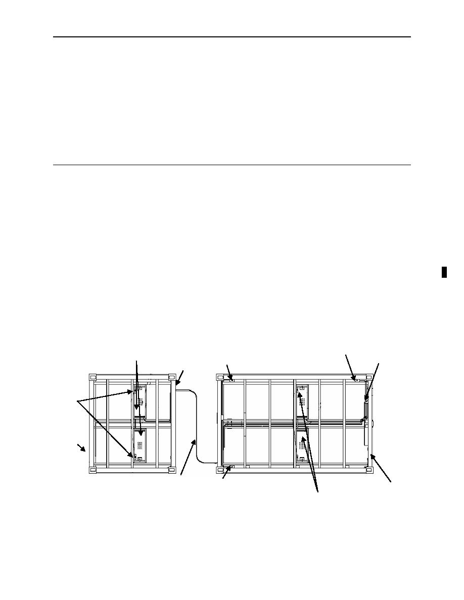
In order to operate the ASLMS electrical components, two 150-ft power cables must be connected from a
20A outlet of a PDISE to the FPU-12 container distribution box located to the right of the bail bar. The
PDISE is connected to a power generator or facility power. This connection provides A/C power to the
120VAC GFCI receptacles and the FPU-12 DC transformer. The FPU-12 DC transformer converts
120VAC power to 12VDC to power the overhead light fixtures inside of the containers. An auxiliary cable
runs from the distribution box located at the rear of the FPU-12 to the distribution box located at the front
of the FPU-8 to operate the FPU-8 lights. There are two 120VAC outlet connectors located on the
distribution box on the rear of the FPU-8 that allows for the connection of additional ASLMS systems in a
series. It is not recommended to connect more than two ASLMS systems in series.
A/C Main Components
R1
120 VAC 20A
R2
DUPLEX OUTLET GFI (TYP3)
120 VAC 2DA
LIGHT STORAGE BOXES
CONNECT TO L2
DUPLEX RECEP GFI
12 VDC
CONNECT TO L2
120 VAC/12 VDC
BOX "B"
ENCLOSED IN M/P
NONMETALLIC
ENCLOSURE
JUNCTION
(VENTILATED)
BOXES
CONNECT TO L1
F/12 VDC
BOX "C"
FRONT
R3
9-FOOT
BOX "A"
LIGHT STORAGE
120 VAC 20A
CABLES
BOXES
DUPLEX OUTLET GFI (TYP3)
12 VDC
CONNECT TO L2
0008 00-1
Change 1


