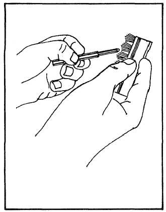
Figure 6-24. Cleaning Nozzle Valve
surfaces to seal properly will result in leakage to the
return or to the outside of the nozzle. See Figure 6-25.
(2)
Inspect the retainer nut (7) for cracks and
re-place it if damaged.
(3)
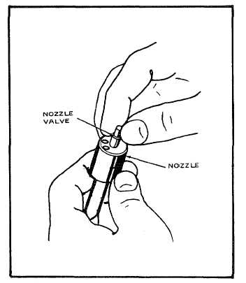
Check the stem and the body of the nozzle.
When both parts are wet with fuel oil, no sticking should
be evident. Pull the valve out of the nozzle about one-
third of its length. When released, the valve should slide
freely back to the seat. Foreign matter or scratches on
the valve will cause it to stick. Carefully inspect before
installing the valve. See Figure 6-26.
d.
Repair or Replacement. Refer to paragraph 6-
3.c for general repair or replacement instructions.
(1)
If necessary, recondition nozzle and inter-
mediate disc surfaces by lapping.
(2)
Replace all threaded parts having worn,
stripped or damaged threads.
c.
Assembly. To assemble the fuel injector
assembly, proceed as follows:
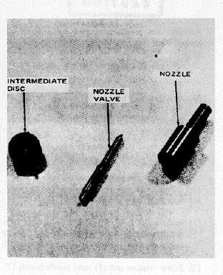
Figure 6-25. Inspecting Mating Surfaces
Figure 6-26. Checking Freedom of Valve in Nozzle
6-61