When air is released, the return spring forces the piston and rod back to static position in advance of the hydraulic cylinder
The stroke Indicator rod follows the piston.
b Hydraulic Master Cylinder The standard master cylinder housing includes a brake fluid reservoir which is joined
to the cylinder bore by intake and compensating (by-pass) ports.
In static position, fluid by-passes to compensate the closed hydraulic system for temperature expansion and contraction or
seepage. During an application, initial piston movement seals off the by-pass, then the stroke displaces fluid, through an
outlet check valve, into the system and pressure builds when this fluid movement ceases. A primary cup, ahead of the
piston, seals the pressure system and the piston carries a secondary seal cup which prevents fluid loss at the open rear of
the cylinder.
Upon release, a return spring forces the piston back to its stop faster than the displaced fluid can unseat the check valve
and return, and a vacuum forms. Reservoir fluid ahead of the secondary cup is sucked through passages in the piston
face, supercharging the system, and the fluid excess by-passes into the reservoir. The return spring also seats the outlet
check valve to trap up to 18 psi residual pressure in the system. Residual pressure assists system sealing and raises the
fluid boil point. The check valve also assists the service "bleeding" operation.
8-3.
MAINTENANCE OF THE POWER CLUSTER
a. Should even a small air leak (slow bubbling when covered with suds) or a hydraulic pressure internal leak
develop, a unit in brake service should be deadlined to avoid the possibility of a hazardous sudden complete failure. Many
vehicle operators prefer scheduled maintenance.
b. At Lube or Oil Change: Clean dirt from area of fluid filler cap Remove cap and fill reservoir to within 1/2 to 3/8
inch of the top. For best results use super heavy duty brake fluid, SAE 70R-3, Wagner Lockheed No. 21B.
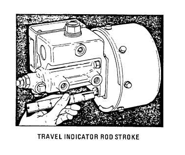
c. At Brake Adjustment - Inspection Brake hnlng clearance adjustment is needed when the stroke of the cluster
travel indicator rod approaches
1 - 1-1/4 mches on units provding 1-1/2 inches total stroke
2 - 2-1/4 inches on units providing 2-9/16 inches total stroke
Also check cluster air cylinder for dents and leaks, hose or pipe connections for leaks and wear, arid hydraulic cylinder for
an internal pressure leak.
8-2