TM 5-4940-200-35
(3) Refer to TM 5-4940-200-12 and reconnect
24. Shop Set Body
the governor drive cable.
a. Removal.
(4) Refer to paragraph 36 and install the
power takeoff universal joint and shaft
(1) Remove all tools and accessories from the
assembly.
compartments.
Store the various
(5) Install all tools and accessories in the
components in containers marked to
compartment from which they were
identify the locations in order to facilitate
removed. (Refer to TM 5-4940-200-12 for
replacement in the proper compartments.
location.)
(2) Refer to paragraph 36 and remove the
power takeoff universal joint and shaft
assembly.
(3) Refer
to
TM
5-4940-200-12
and
disconnect the governor drive cable at the
governor adapter drive.
(4) Refer
to
TM
5-4940-200-12
and
disconnect the overspeed relay wiring
harness from the engine ignition switch
and free the relay wiring harness from the
truck.
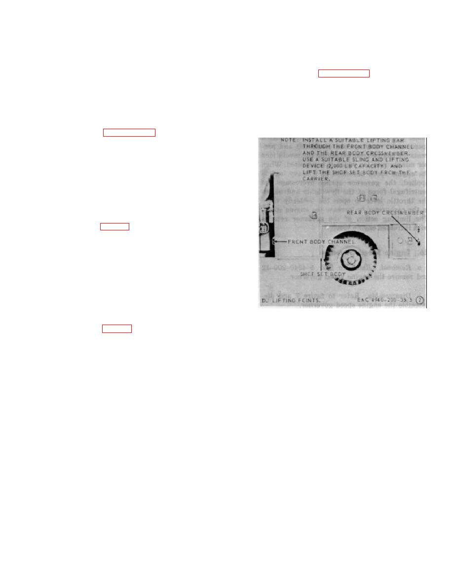
(5) Refer to figure 6 and remove the shop set
body from the carrier.
Caution
Be sure to provide suitable support
for the shop set body after removal
from the carrier; otherwise, damage
to the power takeoff guard or power
takeoff may result.
b. Installation.
Reference D
(1) Refer to figure 6 and install the shop set
Figure 6-Continued.
body.
(2) Refer to TM 5-4940-200-12 and re connect
the overspeed relay wiring harness to the
engine ignition switch.
19


