TM 5-4940-200-35
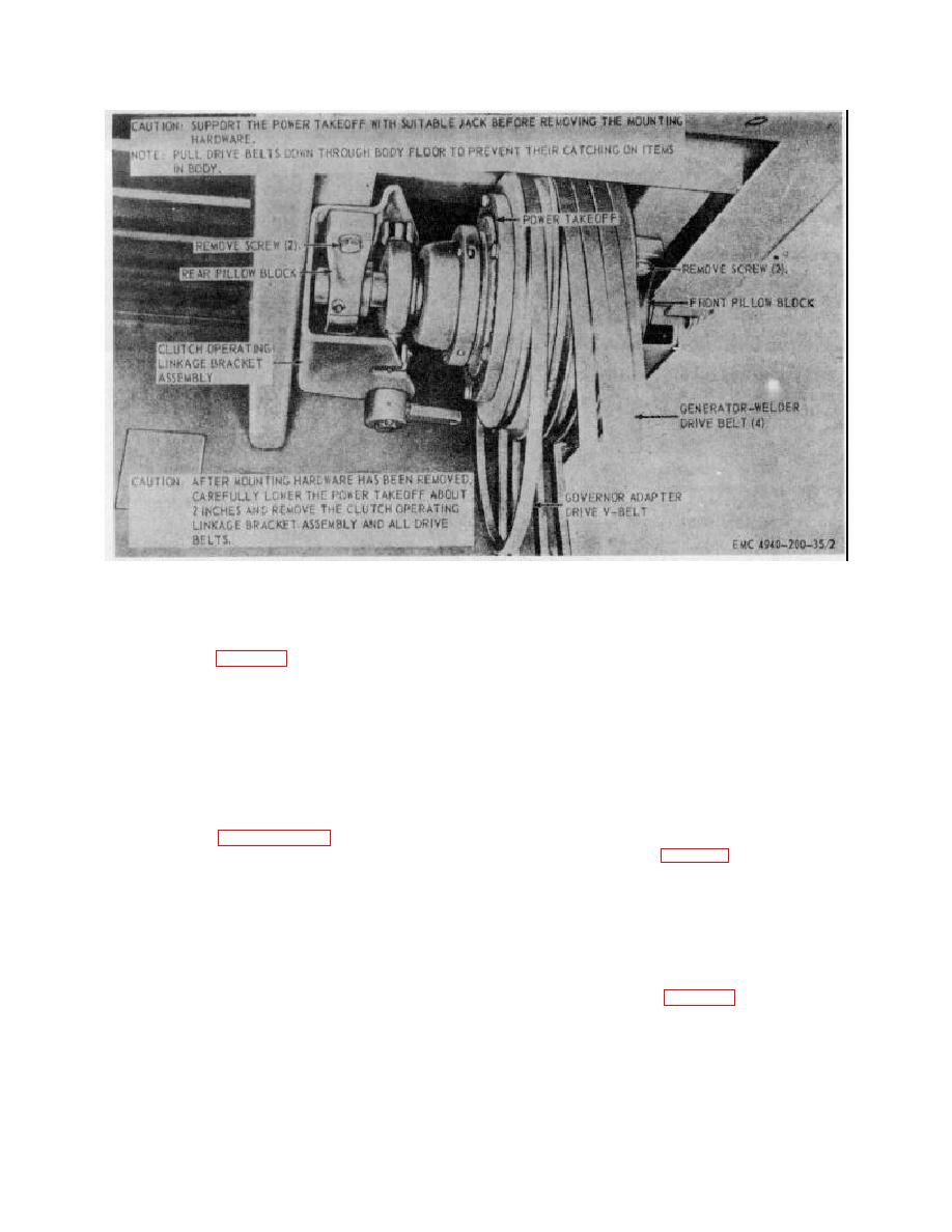
Figure 3. Power takeoff, removal and installation.
b. Installation.
(6) Refer to TM 5-4940-200-12 and install the
power takeoff guard.
(1) Refer to figure 3 and install the power
takeoff.
22. Generator-Welder and Generator Welder Base
a. Removal
Note
Support the power takeoff with a
(1) Refer to TM 5-4940-200-12 and remove
suitable jack and be sure to reinstall
the lifting eye and generator welder top
the clutch operating linkage bracket
cover.
On model CMU-5 shop sets,
assembly
before
installing
the
remove the engine overspeed relay
mounting hardware.
resistor and switches from the generator-
(2) Refer to paragraph 36 and install the
welder.
power takeoff universal joint and shaft
(2) Refer to figure 4 and remove the model
assembly.
SECM generator-welder and generator-
(3) Refer to TX 5-4940-200-12 and connect
welder base.
Remove model CMU-5
the lower linkage to the clutch operating
generator-welder and generator welder
linkage bracket assembly.
base in a similar manner.
(4) Refer to TM 5-4940-200-12 and install the
governor adapter drive V-belt on the
b. Installation.
governor adapter drive pulley.
(5) Install the generator-welder drive belts on
(1) Refer to figure 4 and install the model
the generator-welder pulley. Refer to TM
SECM generator-welder and genera
5-4940-200-12 and adjust the generator-
welder drive belts.
15


