f. Grounding Shop Set. Drive a metal ground rod
frequency of the incoming current, as shown by the
into the ground adjacent to the shop set. Attach a
frequency meter, either 50 or 60 cycles, and set the
No. 6 bare copper wire between the shop set ground
power selector switch on CITY. Conversion to shop
terminal (fig. 2-9 ) and the ground rod.
set generated power is accomplished by stopping all
shop set functions, turning switches to OFF and by
WARNING
removal of the external power source, setting the
Static electricity and leakage currents
from electric equipment can build up in
frequency switch to desired frequency output,
the chop set and cause injury or death to
either 50 or 60 cycles, and the power selector switch
personnel unless the equipment is
to GENERATOR. The output from the receptacles
properly grounded.
on the control panel is either 120-volt, single-phase,
at a maximum of 15 amperes, or 240-volts, single-
2-3. Equipment Conversation
phase, at a maximum of 10 amperes. To use either
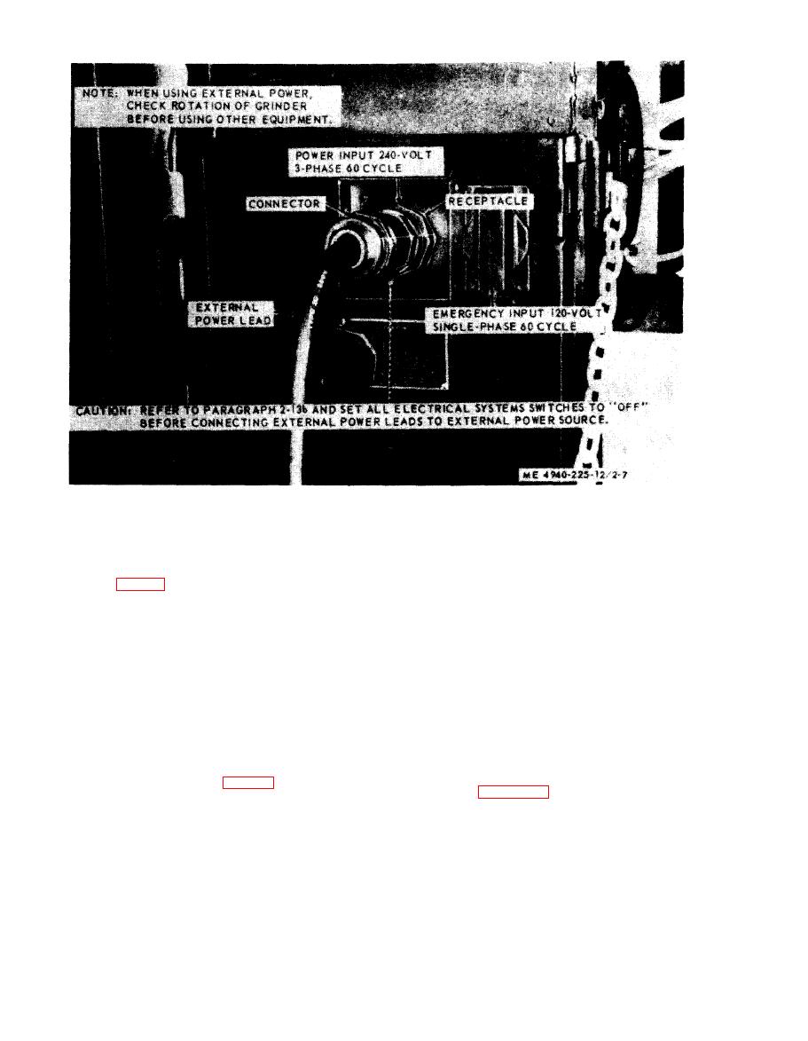
The d ynamotor-welder can be driven by the truck's
120 or 240-volts from either GENERATOR or
engine through the power take off or by a 240-volt
CITY power source, select the appropriate output
AC external power source. If an external power
receptacle or receptacles and the applicable power
source is to be used, connect the power source and
selector switch and frequency switch setting as
set the frequency switch (fig. 2-8) to match the
indicated in figure 2-8.


