
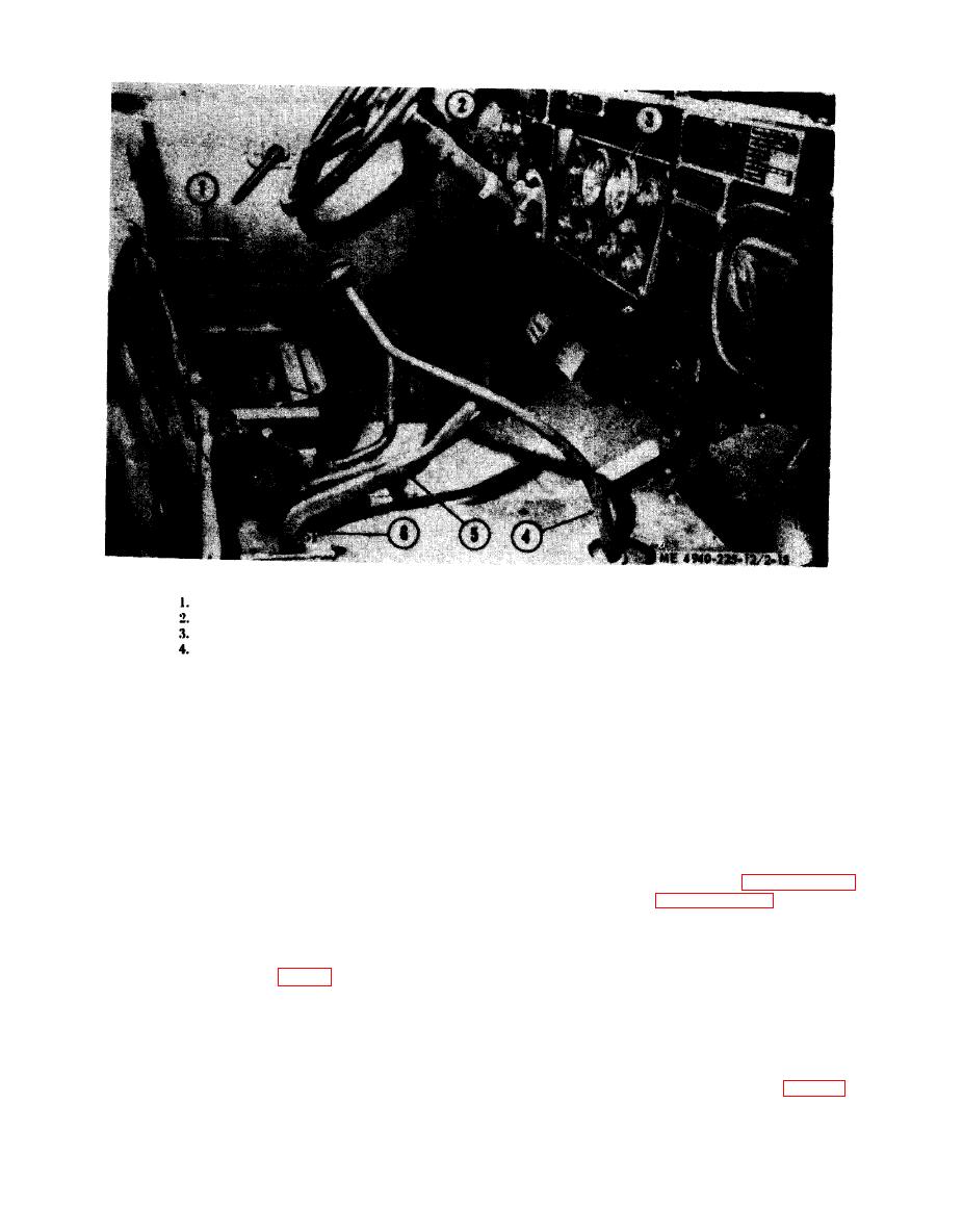
5.
Winch lever
Hand brake
6.
Locking pin
Hand throttle
7.
Transfer lever
Tachometer
8.
Power take-off lever
Transmission shift lever
CAUTION
T o prevent damage of components,
Release governor control knob and push in to
make certain levers are positioned as
dash and lock.
above, before movement of vehicle.
b. Unlock hand throttle and push in to dash.
c. Depress clutch, shift transmission lever to
neutral position.
8. Operation on Internal Power (Shop set
d. Disengage power take-off by placing power
Equipment).
take-off lever fully down. Remove pin from transfer
(1) Place all circuit breakers and switches on
case lever and position lever in desired gear range.
the control panel in the OFF position.
CAUTION
(2) Start the engine. Refer to paragraph 2-8
To prevent damage to components,
for Model SEORLT, or paragraph 2-9 for Model
make certain levers are positioned as
SEORL.
above, before movement of vehicle.
(3) For 60-cycle A.C. Output, adjust speed
2-12. Stopping (Model SEORL)
control to give tachometer reading of 1,200 rpm,
(4) For 50-cycle A.C. Output, adjust speed
Push hand throttle (2, fig. 2-1 S ) in, reducing
control to give tachometer reading of 1,000 rpm.
engine speed to idle.
b. Depres clutch, and shift transmission to
(5)
Set
power
selector
switch
to
neutral position.
c. Disengage power take-off by placing lever (8)
d e s i r e d frequency; either 50 or 60 cycle, but,
fully down.
compatible with the speed adjustment.
d. Remove pin (6) from transfer lever (7) and
(6) Place the control circuit breaker (fig. 2-1 3)
ptmition in desired gear range.
to ON position , and press the dynamotor start
