
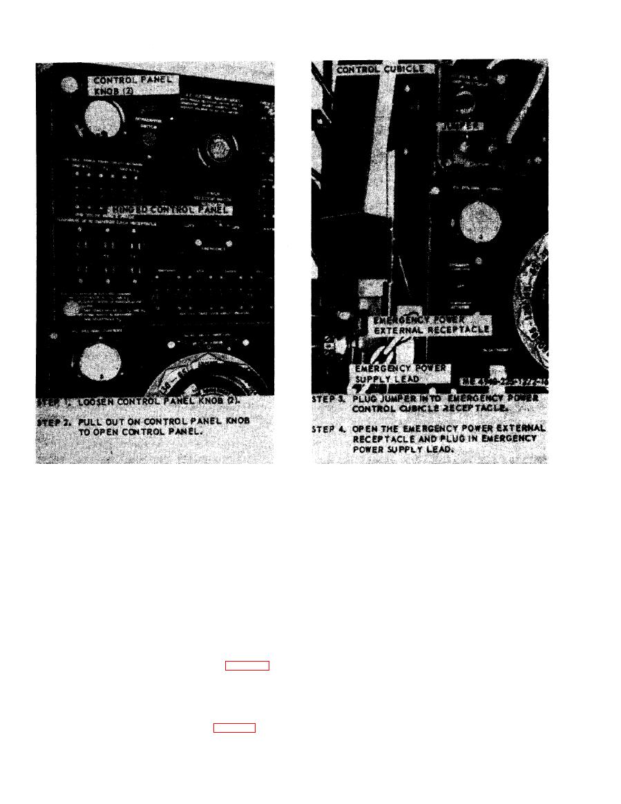
Figure 2.16. Connecting the emergency power supply.
within the selected range with the D.C. ampere
(d) Observe the frequency meter and set the
adjusting rheostat. The voltage and amperage will
frequency switch to either 50 or 60 cycles as in-
be indicated on the D.C. meters.
dicated by the meter.
(e) Place R3 circuit breaker in the ON
NOTE
The dynamotor start switch should not be energized.
position.
Under these operating conditions, all A.C. circuits are
(f) 120-V power is available from R3 duplex
de-energized.
r e c e p t a c l e s ONLY. Shop set lights are also
e . Welder Operation. Refer to TM 9-237 for
operational.
welding techniques.)
d. Operation with Power Selector Switch in OFF
(1) Refer to paragraph a above, and energize
Position.
the system with internal power; refer to paragraph
(1) To develop D.C. current for welding,
b above, and energize the system with external
when A. C, current for operating shop set is not
power, or, refer to paragraph d above.
desired, turn the power selector switch (fig. 2-13)
(2) Connect electrode and ground cable to
OFF. Start the engine and accelerate to 1,200
d y n a m o t o r - w e l d e r output terminals (positive
rpm.
electrode and negative ground ).
(2) The required D.C. current is now available
(3) Place the polarity switch in the desired
at the positive and negative welding terminals.
position.
Turn the D.C. ampere selector switch (fig. 2-13) to
the desired ampere range and adjust the amperage
