
TM 9-4933-223-13&P
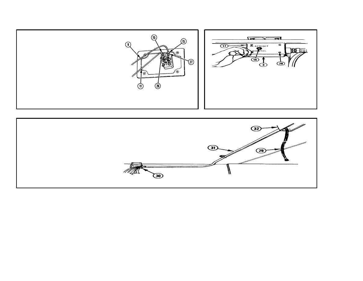
11 BLACK WIRE NO.
8 (11).
a.
Connect to terminal no. 1 (26).
b.
Reinstall terminal screw (15).
12 BLACK WIRE NO.
4B (9).
13 COVER (17) WITH TOGGLE SWITCH S8
a.
Connect to terminal no. 4 (27).
(16).
b.
Reinstall terminal screw (15).
a.
Place on switchbox S7/S8 (3).
b.
Install four screws (28).
NOTE
Perform the procedure in
step 14, using harness
assembly with ends of nine
wires taped together.
14. HARNESS ASSEMBLY (29).
a.
Pull from switchbox S9 (30)
through conduit (31) into "T"
conduit box J21 (32).
3-67
