
TM 9-4940-421-14
4-37. V-BELT.
b. Installation. Install drive motor in reverse order
Adjustment.
of removal.
a. Remove ten screws and remove fan guard.
b. Loosen four hold down bolts and nuts and slidc
a. To increase both CUT-IN and CUT-OUT turn
the motor on the base to allow the belt a 1/2 inch deflec-
pressure adjusting screw clockwise (fig 4-14).
tion between pulleys. Tighten the four hold down bolts
b. To increase DIFFERENTIAL and maintain same
and nuts.
CUT-IN pressure, turn differential screw at edge
clockwise (fig 4-14).
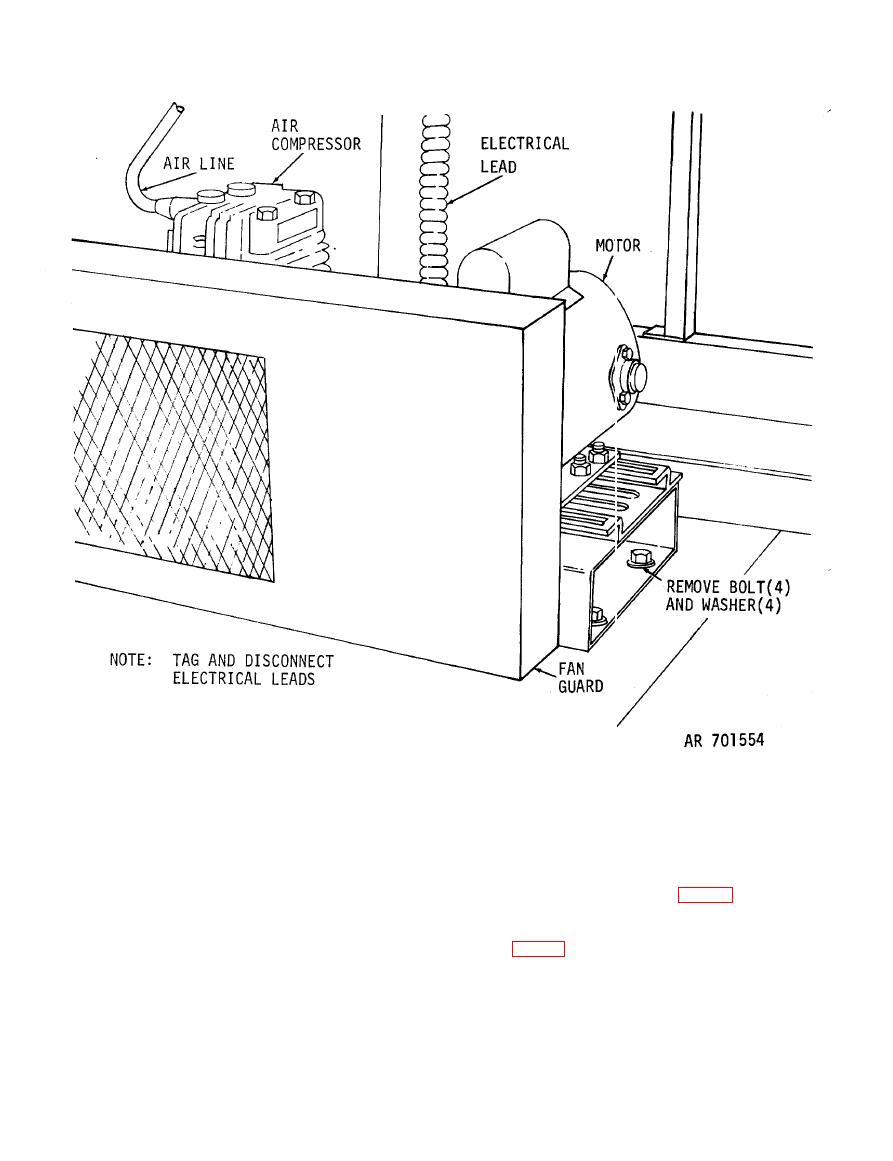
a. Removal
WARNING
(1) Disconnect and tag electrical lead.
Do not block POP- OFF valve,
(2) Remove fan guard and V-belt.
NOTE
(3) Remove four bolts and nuts and remove drive
CUT-IN pressure should be set at 80 psi and differential
motor.
should be set to CUT-OUT at 100 psi.
