
TM 10-5411-236-13&P
0053 00
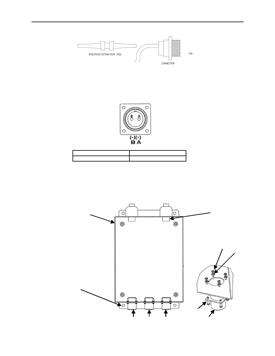
18. Slide out insertion tool.
19. Following the same procedures in steps 12 and 17 to attach the wires marked L2 to sockets of the
right female connector.
20. Using installation steps 3 through 7, connect DC wires (see table and illustration below for wire
arrangement).
RED
A
BLACK
B
21. Reattach the female receptacles to the distribution box with the four #5 40 x 1/2-inch fillister head
screws (8), hex head nuts (6) and lock washers (7) using a flat head screw driver and 5/16-inch open
end wrench.
22. Verify electrical continuity for "from to" path with an ohmmeter and remove tags.
1
2
7
8
3
9
4
5
6
10
0053 00-5

