
TM 1-4920-436-13&P
OPERATOR INSTRUCTIONS
ENGINE SHOP
CONNECTING COMPRESSED AIR AND WATER
INITIAL SETUP:
References
Tools and Special Tools
General Mechanics Tool Kit
(WP 0060 00, Table 2, Item 104 )
Equipment Condition
Personnel Required
Functional
CMF 15 Series (1)
CONNECTING COMPRESSED AIR
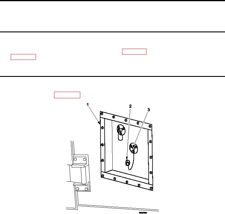
The shop is provided with connections for compressed air and water. These connections are located on the ser-
vices utility panel see (WP 0002 00, Figure 1).
Figure 1.
Removing Protective Dust Cap.
1.
Remove protective dust cap (Figure 1, Item 2) from air feed-thru connector assembly (Figure 1, Item 3) at
services utility panel (Figure 1, Item 1).
0016 00-1