
0034 00
TM 1-4920-436-13&P
REMOVAL CONTINUED
KICK PLATE CONTINUED
2.
With screwdriver, pull kick plate (Figure 1, Item 1) outward on each side. Kick plate (Figure 1, Item 1) should
easily dislodge from cabinet.
INSTALLATION
KICK PLATE
1.
Align kick plate tabs (Figure 1, Item 2) with pre-drilled holes in cabinet s pallet feet.
2.
Secure kick plate (Figure 1, Item 1) to cabinet by pushing irmly. Kick plate (Figure 1, Item 1) should easily
snap in place.
REMOVAL
DRAWERS, SLIDES, AND SHELVES
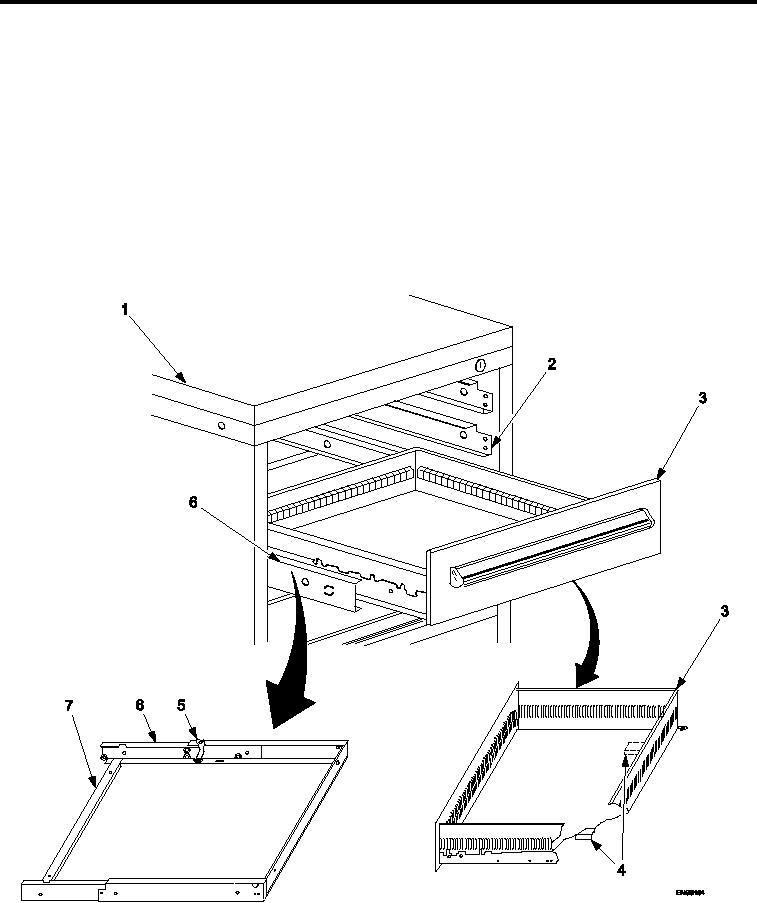
Figure 2.
Drawers, Slides, and Shelves Remove and Install.
1.
To remove drawer (Figure 2, Item 3), pull drawer (Figure 2, Item 3) outward until it stops.
0034 00-2