
TM 1-4920-436-13&P
FIELD MAINTENANCE
ENGINE SHOP
MAINTENANCE INSTRUCTIONS FOR CABINET ASSEMBLIES
INITIAL SETUP:
Tools and Special Tools
Personnel Required
Drill Set, Twist (WP 0060 00, Table 2, Item 102 )
CMF 44-B Metal Worker (1)
General Mechanics Tool Kit
CMF 15 Series (3)
(WP 0060 00, Table 2, Item 104 )
References
Paint Brush (WP 0060 00, Table 2, Item 107 )
Portable Electric Drill (WP 0060 00, Table 2, Item 108 )
Torque Wrench, 0-600 in. lbs
TM 1-1500-204-23
(WP 0060 00, Table 2, Item 109 )
Equipment Condition
Materials/Parts
Functional
Enamel, Gray (WP 0066 00, Item 2)
NOTE
During installation of components same hardware should be used so as to maintain original
integrity of shop set.
REMOVAL
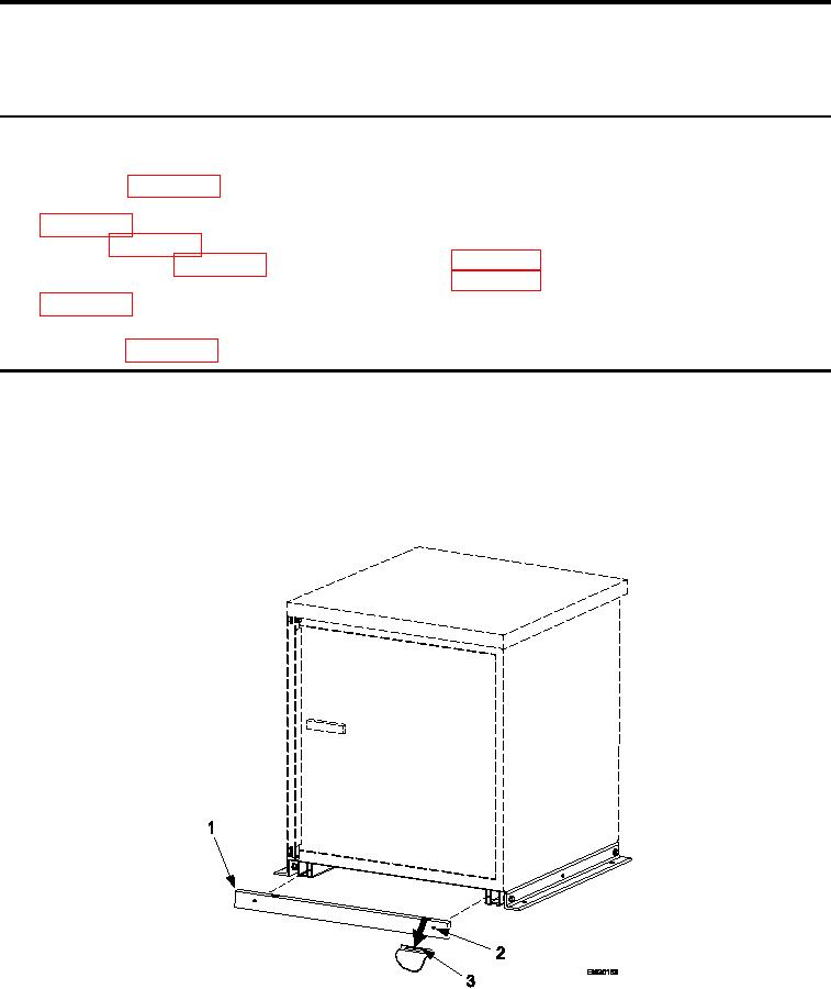
KICK PLATE
Figure 1.
Kick Plate Remove and Install.
1.
Wedge screwdriver at indentation (Figure 1, Item 3) on each side of kick plate (Figure 1, Item 1).
0034 00-1