
TM 1-4920-438-13&P
0034 00
RAISING HINGED FLOOR - CONTINUED
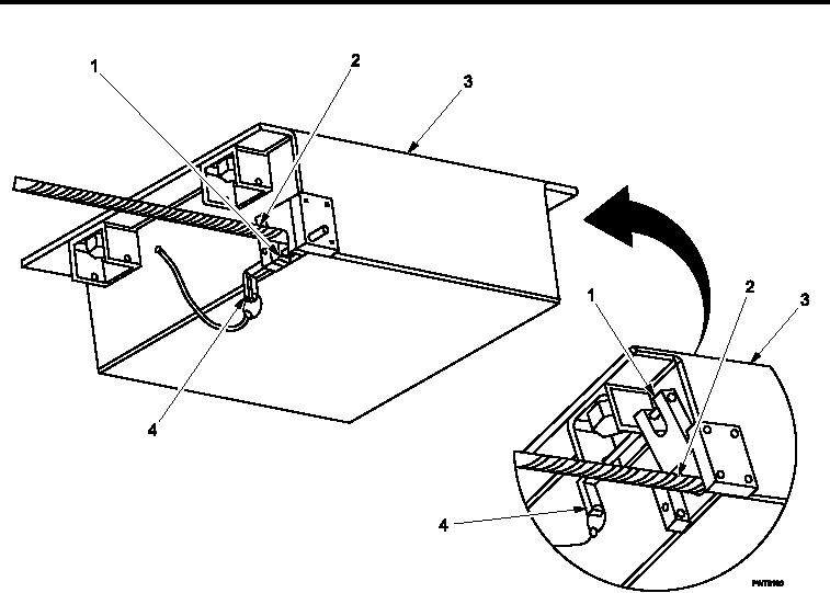
Figure 9.
Load Balancers Slide Stops, Lower Position.
7.
Remove lockout pins (Figure 7, Item 4) from upper position on both load balancers (Figure 7, Item 3).
8.
Close slide stops (Figure 7, Item 1) against support cables (Figure 7, Item 2) on load balancers (Figure 7,
Item 3).
9.
Replace lockout pins (Figure 7, Item 4) in lower position on load balancers (Figure 7, Item 3).
0034 00-9