
TM 1-4920-440-13&P
0005 00
ASSEMBLY AND PREPARATION FOR USE CONTINUED
NOTE
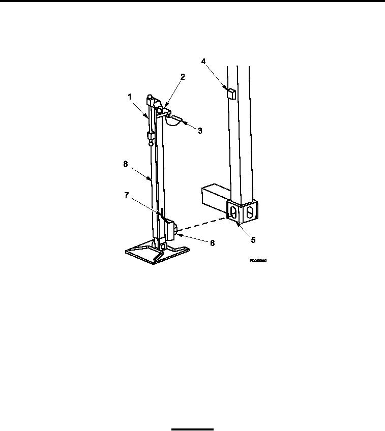
Stencil on leveling support jack assemblies indicate handle rotation to raise or lower jack.
Figure 2.
Leveling Support Jack Install.
3.
Ensure leveling support jack assemblies (Figure 2, Item 8) are lowered completely.
4.
Place upper jack attachment insert (Figure 2, Item 2) on upper jack support bracket (Figure 2, Item 4) on
corner post.
5.
Insert jack attachment (Figure 2, Item 6) into lower leveling support itting (Figure 2, Item 5) of shelter.
6.
Turn locking handle (Figure 2, Item 7) to rotate jack attachment on leveling support jack assembly (Figure 2,
Item 8) to lock.
7.
Rotate handle (Figure 2, Item 1) counterclockwise on leveling support jack assembly (Figure 2, Item 8) to
raise until safety pin (Figure 2, Item 3) can be installed.
8.
Install safety pin (Figure 2, Item 3).
9.
Repeat steps Steps 3 through 8 at three remaining corners.
CAUTION
Leveling support jack assemblies must be raised simultaneously to prevent excessive strain on
leveling support jack assemblies or shelter. Shelter must be raised a minimum of 3 inches (7.6
cm) off ground.
10. Simultaneously raise leveling support jack assemblies (Figure 2, Item 8) at each corner of shelter.
0005 00-3