
TM 1-4920-440-13&P
0005 00
POSITIONING HINGED SIDEWALL
Figure 6.
Positioning Hinged Wall.
1.
Remove two sidewall support braces from shelter BII box (WP 0002 00, Figure 2, Item 5 or Figure 3, Item 6).
2.
Raise hinged sidewall and hold in position.
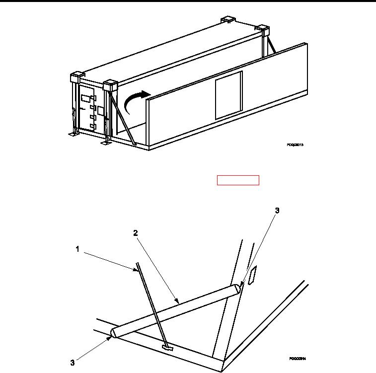
Figure 7.
Sidewall Support Braces.
3.
Install two sidewall support braces (Figure 7, Item 2) in brace cups marked "A" (Figure 7, Item 3) on hinged
loor and sidewall behind support cable (Figure 7, Item 1).
0005 00-7