
0045 00
TM 1-4920-440-13&P
INSPECTION OF INSTALLED ITEMS CONTINUED
KEY CABINET (1036659) CONTINUED
1.
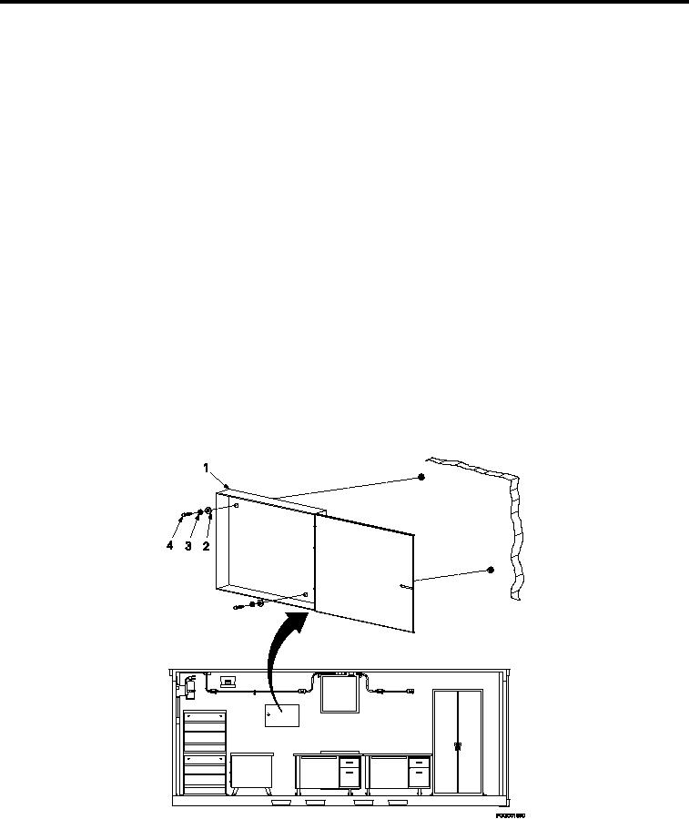
Inspect key cabinet (Figure 1) for damage. Replace as necessary.
2.
Inspect all key cabinet hardware (Figure 1, Item 2, 3, and 4) for rust, cracks and rounded heads. Replace as
necessary.
REMOVAL
Remove four bolts (Figure 1, Item 4), four lock washers (Figure 1, Item 3), four lat washers (Figure 1, Item 2)
and key cabinet (Figure 1, Item 1).
INSTALLATION
1.
Position key cabinet (Figure 1, Item 1) by aligning bolt holes with wall inserts.
2.
Install four bolts (Figure 1, Item 4), four lock washers (Figure 1, Item 3), and four lat washers (Figure 1, Item
2), attaching key cabinet (Figure 1, Item 1) to shelter wall.
Torque bolts (Figure 1, Item 4) 160-190 in. lbs.
3.
INSPECTION OF INSTALLED ITEMS
KEY CABINET (SC4920-99-CLA66)
NOTE
During installation of components, same hardware should be used so as to maintain original
integrity of shop set.
Figure 2.
Key Cabinet (SC4920-99-CLA66).
0045 00-2