
0038 00
TM 1-4920-441-13&P
INSTALLATION
KICK PLATE
1.
Align kick plate tabs (Figure 1, Item 2) with pre-drilled holes in cabinet s pallet feet.
2.
Secure kick plate (Figure 1, Item 1) to cabinet by pushing irmly. Kick plate (Figure 1, Item 1) should easily
snap in place.
REMOVAL
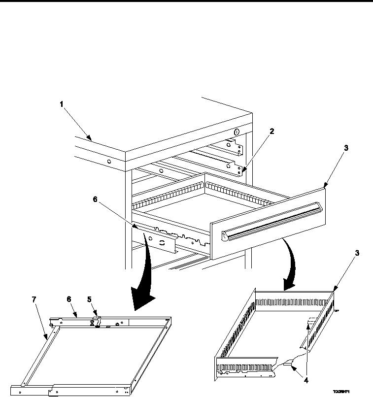
DRAWERS, SLIDES, AND SHELVES
Figure 2.
Drawers, Slides, and Shelves Remove and Install.
1.
To remove drawer (Figure 2, Item 3), pull drawer (Figure 2, Item 3) outward until it stops.
2.
Lift drawer (Figure 2, Item 3) upward to clear drawer stops (Figure 2, Item 4) over the cross member (Figure
2, Item 7) and pull the drawer (Figure 2, Item 3) all the way out of the cabinet (Figure 2, Item 1).
3.
To remove slide (Figure 2, Item 6), pull the slide (Figure 2, Item 6) outward until it stops.
4.
Lift upward on latches (Figure 2, Item 5) located on each side of slide (Figure 2, Item 6).
0038 00-2