
TM 1-4920-441-13&P
FIELD MAINTENANCE
TOOL CRIB SHOP
MAINTENANCE INSTRUCTIONS FOR CABINET ASSEMBLIES
INITIAL SETUP:
Personnel Required
Tools and Special Tools
CMF 44-B Metal Worker (1)
Drill Set, Twist (WP 0059 00, Table 2, Item 102 )
CMF 15 Series (3)
General Mechanics Tool Kit
References
(WP 0059 00, Table 2, Item 104 )
TM 1-1500-204-23
Paint Brush (WP 0059 00, Table 2, Item 107 )
Portable Electric Drill (WP 0059 00, Table 2, Item 108 )
Materials/Parts
Equipment Condition
Enamel, Gray (WP 0066 00, Item 2)
Functional
NOTE
During installation of components same hardware should be used so as to maintain original
integrity of shop set.
REMOVAL
KICK PLATE
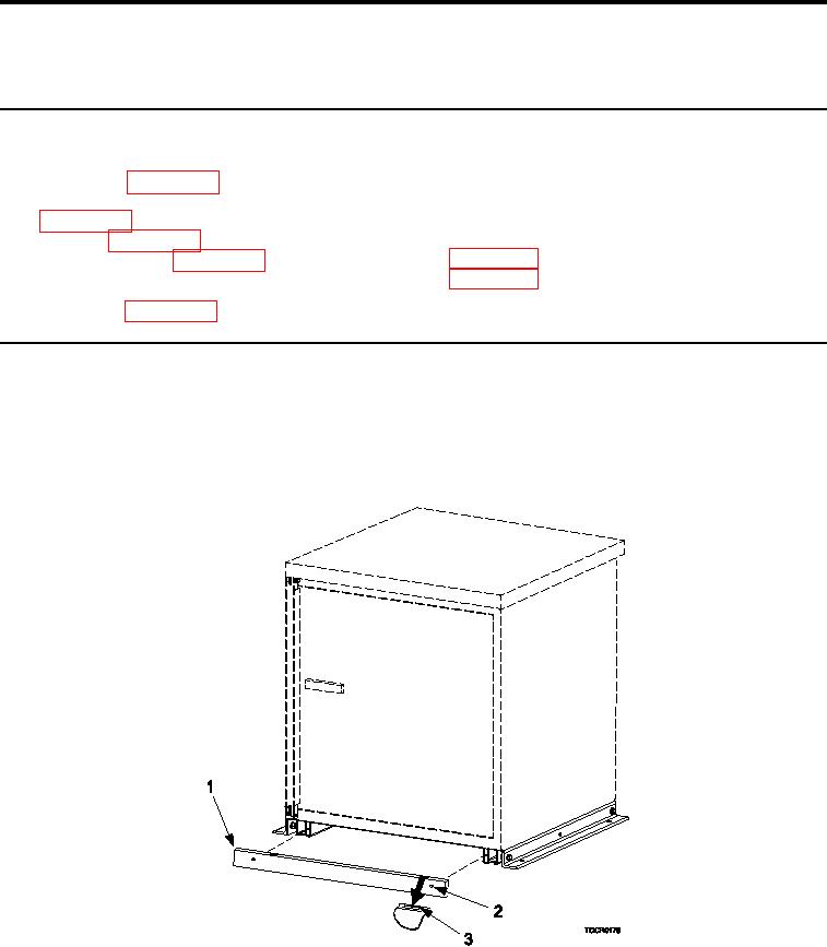
Figure 1.
Kick Plate Remove and Install.
1.
Wedge screwdriver at indentation (Figure 1, Item 3) on each side of kick plate (Figure 1, Item 1).
2.
With screwdriver, pull kick plate (Figure 1, Item 1) outward on each side. Kick plate (Figure 1, Item 1) should
easily dislodge from cabinet.
0038 00-1