
TM 1-4920-441-13&P
0038 00
REMOVAL CONTINUED
DRAWERS, SLIDES, AND SHELVES CONTINUED
5.
Once latches (Figure 2, Item 5) are disengaged, slide (Figure 2, Item 6) will pull all the way out of cabinet
(Figure 2, Item 1).
6.
To remove shelf, lift shelf off shelf brackets and pull all the way out of the cabinet (Figure 2, Item 1).
INSTALLATION
DRAWERS, SLIDES, AND SHELVES
1.
To install shelf, align and rest shelf onto shelf brackets.
2.
To install slide (Figure 2, Item 6), align slide (Figure 2, Item 6) to slide bracket (Figure 2, Item 2) and push into
cabinet (Figure 2, Item 1).
3.
Ensure latches (Figure 2, Item 5) are in a forward down position.
4.
To install drawer (Figure 2, Item 3), pull slide (Figure 2, Item 6) all the way out for easy access.
5.
Align drawer (Figure 2, Item 3) into the slides (Figure 2, Item 6) and push inward until it stops.
6.
Lift drawer (Figure 2, Item 3) upward to clear drawer stops (Figure 2, Item 4) over the cross member (Figure
2, Item 7) and push drawer (Figure 2, Item 3) all the way into cabinet (Figure 2, Item 1).
INSPECTION OF INSTALLED ITEMS
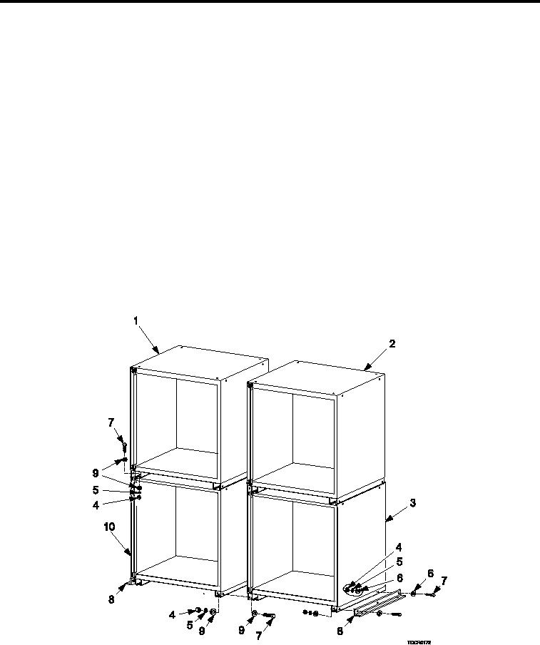
4 DRAWER CABINET (A) AND SHELF CABINET (A) AND 4 DRAWER CABINET (B) AND SHELF CABINET (B)
Figure 3.
4 Drawer Cabinet (A), and Shelf Cabinet (A), 4 Drawer Cabinet (B), and Shelf Cabinet (B).
1.
Inspect cabinet assembly and work surface (Figure 3) for damage. Replace as necessary.
0038 00-3