
TM 1-4920-441-13&P
0049 00
INSTALLATION CONTINUED
WATER FEED-THRU CONNECTOR ASSEMBLY CONTINUED
3.
Install all but one screw (Figure 6, Item 2), have assistant install lat washers (Figure 6, Item 3), lock washers
(Figure 6, Item 4), and nuts (Figure 6, Item 5) inside of shelter and secure.
4.
Replace lanyard (Figure 6, Item 6) on outside of shelter and install remaining screw (Figure 6, Item 2).
5.
Have assistant install lat washer (Figure 6, Item 3), lock washer (Figure 6, Item 4), second lanyard (Figure 6,
Item 6), and nut (Figure 6, Item 5) on inside of shelter.
6.
Tighten screws (Figure 6, Item 2).
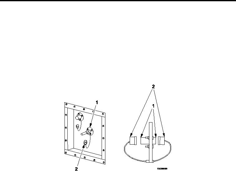
INSPECTION OF INSTALLED ITEMS
AIR FEED-THRU CONNECTOR ASSEMBLY
Figure 7.
Inspect Air Feed-thru Connector Assembly.
1.
Inspect condition of threads on both ends of air feed-thru connector assembly (Figure 7, Item 1). Replace as
necessary.
2.
Ensure that protective dust caps (Figure 7, Item 2) are attached.
3.
Ensure weld on connector is not cracked or broken. If defective, replace.
0049 00-5