
0049 00
TM 1-4920-441-13&P
INSTALLATION CONTINUED
AIR FEED-THRU CONNECTOR ASSEMBLY CONTINUED
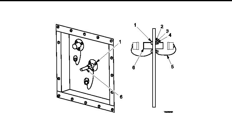
Figure 12.
Attach Air Feed-thru Connector Assembly.
3.
Install all but one screw (Figure 12, Item 1), have assistant install lat washers (Figure 12, Item 2), lock
washers (Figure 12, Item 3), and nuts (Figure 12, Item 4) inside of shelter and secure.
4.
Replace lanyard (Figure 12, Item 5) on outside of shelter and install screw (Figure 12, Item 1).
5.
Have assistant install lat washer (Figure 12, Item 2), lock washer (Figure 12, Item 3), second lanyard (Figure
12, Item 5), and nut (Figure 12, Item 4) on inside of shelter.
6.
Tighten screws (Figure 12, Item 1).
END OF WORK PACKAGE
0049 00-8