
0012
TM 1-4920-924-13&P
AVIATION SHOP EQUIPMENT CONTACT MAINTENANCE (AV SECM) SYSTEM MAINTENANCE
INSTRUCTIONS FOR ROADSIDE RACK ASSEMBLY - (CONTINUED)
10. Install sixteen 1/4-20 X 0.63 inch low head screws (Figure 11, Item 31), sixteen self clinching nuts
(Figure 11, Item 32), and four drawer slides (Figure 11, Item 27).
11. Install sixteen 1/4-20 X 0.50 inch low head screws (Figure 11, Item 28), sixteen self clinching nuts
(Figure 11, Item 29) and two shelf assemblies (Figure 11, Item 30).
Second Shelf
3
1
2
4
18
20
19
5
17
14
6
15
16
7
9
12
13
8
11
10
SECM0035
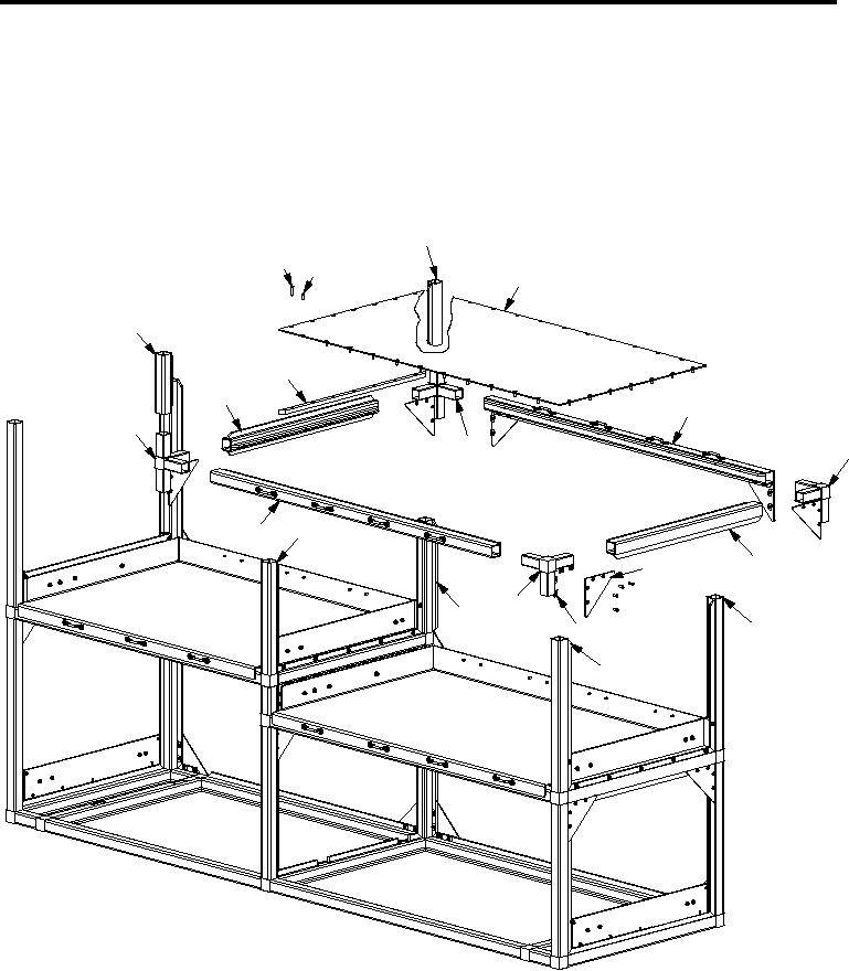
Figure 12. Roadside Rack Assembly Second Shelf
1.
Install two corner castings (Figure 12, Item 14 and 17) into aluminum rail (Figure 12, Item 19).
2.
Install two corner castings (Figure 12, Item 14 and 17) into aluminum rails (Figure 12, Item 5 and 16).
3.
Install two corner castings (Figure 12, Item 6 and 12) into aluminum rail (Figure 12, Item 7).
001219