
0012
TM 1-4920-924-13&P
AVIATION SHOP EQUIPMENT CONTACT MAINTENANCE (AV SECM) SYSTEM MAINTENANCE
INSTRUCTIONS FOR ROADSIDE RACK ASSEMBLY - (CONTINUED)
Fourth Shelf
10
3
4
7
3
8
5
6
1
3
2
9
11
20
12
25
24
22
23
21
13
14
18
17
19
15
16
SECM0032
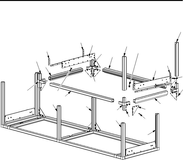
Figure 10. Roadside Rack Assembly Fourth Shelf
1.
Install two corner castings (Figure 10, Item 20 and 25) into aluminum rail (Figure 10, Item 2).
2.
Install two corner castings (Figure 10, Item 20 and 25) into aluminum rails (Figure 10, Item 6 and 22).
3.
Install two corner castings (Figure 10, Item 12 and 18) into aluminum rail (Figure 10, Item 13).
4.
Install two corner castings (Figure 10, Item 12 and 18) into aluminum rails (Figure 10, Item 6 and 22).
5.
Install two aluminum rails (Figure 10, Item 1 and 5) into top of two corner castings (Figure 10, Item 20
and 25).
6. Install two aluminum rails (Figure 10, Item 7 and 10) into top of two corner castings (Figure 10, Item
12 and 18).
7. Install bottoms of four corner castings (Figure 10, Item 12, 18, 20 and 25) into four aluminum rails
(Figure 10, Item 16, 19, 21 and 23).
8. Install thirty-two 1032 x 1.13 inch countersunk screws (Figure 10, Item 15), thirty-two speed nuts
(Figure 10, Item 17) and eight large gussets (Figure 10, Item 14).
9. Install eleven 1032 x 1.13 inch countersunk screws (Figure 10, Item 24), eleven speed nuts (Figure 10, Item
17), onto sides and bottom of one support plate (Figure 10, Item 4) and three shims (Figure 10, Item 3).
10. Install seven 1/420 x 1.75 inch pan head screws (Figure 10, Item 11), seven self clinching nuts
(Figure 10, Item 8), three shims (Figure 10, Item 3) and one drawer slide mounting plate (Figure 10, Item 9).
001216