
0012
TM 1-4920-924-13&P
AVIATION SHOP EQUIPMENT CONTACT MAINTENANCE (AV SECM) SYSTEM MAINTENANCE
INSTRUCTIONS FOR ROADSIDE RACK ASSEMBLY - (CONTINUED)
30
29
28
31
32
27
SECM0034
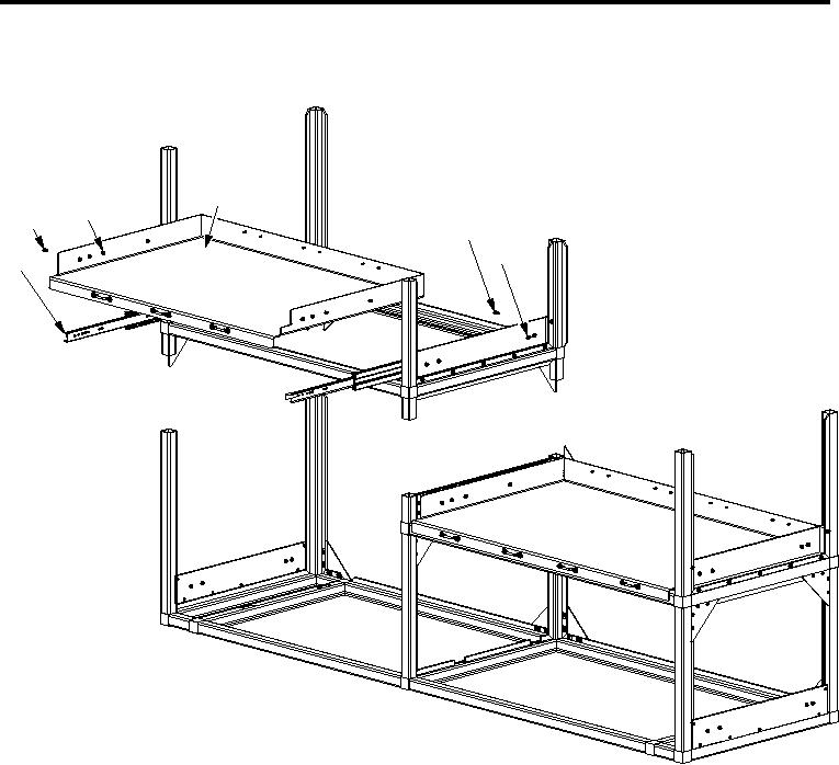
Figure 11.
Roadside Rack Assembly Third Shelf (Sheet 2 of 2).
1.
Install two corner castings (Figure 11, Item 19 and 22) into aluminum rail (Figure 11, Item 2).
2.
Install two corner castings (Figure 11, Item 19 and 22) into aluminum rails (Figure 11, Item 8 and 20).
3.
Install two corner castings (Figure 11, Item 10 and 15) into aluminum rail (Figure 11, Item 13).
4.
Install two corner castings (Figure 11, Item 10 and 15) into aluminum rails (Figure 11, Item 8 and 20).
5.
Install four aluminum rails (Figure 11, Item 1, 4, 7 and 9) into four corner castings (Figure 11, Item 10, 15,
19 and 22).
6.
Install bottoms of four corner castings (Figure 11, Item 10, 15, 19 and 22) into four aluminum rails
(Figure 11, Item 11, 17, 18 and 23).
7.
Install twenty-four 10-32 X 0.63 inch countersunk screws (Figure 11, Item 25), twenty-four speed nuts
(Figure 11, Item 21), and six large gussets (Figure 11, Item 24).
8.
Install seven 10-32 X 1.13 inch countersunk screws (Figure 11, Item 14), and seven speed nuts
(Figure 11, Item 21) into top of support plate (Figure 11, Item 12) and one shim (Figure 11, Item 16).
9.
Install twenty-one 1/4-20 X 1.75 inch pan head screws (Figure 11, Item 26), twenty-one self clinching nuts
(Figure 11, Item 3), three drawer slide mounting plates (Figure 11, Item 5) and nine shims (Figure 11, Item
6).
001218