0016
TM 1-4920-924-13&P
AVIATION SHOP EQUIPMENT CONTACT MAINTENANCE (AV SECM) SYSTEM MAINTENANCE
INSTRUCTIONS FOR POWER INVERTER - (CONTINUED)
5
4
3
6
2
7
1
8
9
OFF
Inverter Power
Power
Low Battery
OFF
On/Off
ON
Overload
High Temperature
Main
output
breaker
16
000004
h
10
11
15
12
13
14
SECM0085
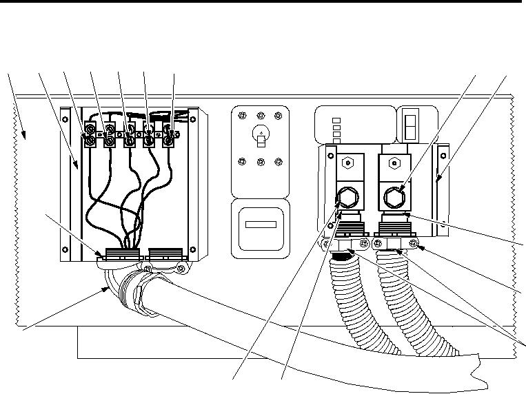
Figure 3.
Power Inverter, Front
3.
With multi-meter, ensure that voltage is not present between the positive (Figure 3, Item 14) and ground
wire (Figure 3, Item 17).
4.
Loosen four screws (Figure 3, Item 15) on two cable clamps (Figure 3, Item 16).
5.
Loosen ground lug (Figure 3, Item 18) on power inverter (Figure 3, Item 1) and pull ground wire
(Figure 3, Item 17) through bottom of cable clamp (Figure 3, Item 16) on bottom of DC input wiring
compartment (Figure 3, Item 4).
6.
Loosen positive lug (Figure 3, Item 13) on power inverter (Figure 3, Item 1) and pull positive wire
(Figure 3, Item 14) through bottom of cable clamp (Figure 3, Item 16) on bottom of DC input wiring
compartment (Figure 3, Item 4).
7.
With multi-meter, ensure there is no voltage between L1 (Figure 3, Item 10), L2 (Figure 3, Item 11) and L3
(Figure 3, Item 12) terminals and the ground terminal (Figure 3, Item 8).
8.
Remove blue wire from the L3 terminal (Figure 3, Item 12).
9.
Remove red wire from the L2 terminal (Figure 3, Item 11).
10.
Remove black wire from the L1 terminal (Figure 3, Item 10).
11.
Remove white wire from the neutral terminal (Figure 3, Item 9).
12.
Remove green wire from the ground terminal (Figure 3, Item 8).
13.
Remove locknut (Figure 3, Item 20) from 90 degree elbow (Figure 3, Item 19) and remove wires from
bottom of AC wiring compartment (Figure 3, Item 3).
00164

