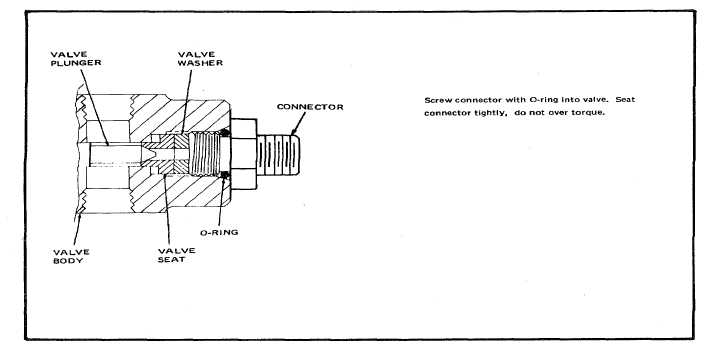
Figure 6-4. Seating Priority Valve Connector.
(1)
Unscrew and remove head (5) from bowl
(1).
(2)
Remove element (2) from bowl (1).
(3)
Remove two backup rings (3), and o-ring
(4) from filter head (5).
b.
Cleaning. Refer to paragraph 6-3.a. for general
cleaning instructions.
(1)
Flush the filter bowl clean with P-D-680,
Type II, or equivalent.
(2)
Clean the filter head with the flushing agent.
(3)
Allow bowl and head to air dry until odor of
the flushing agent disappears.
c.
Inspection. Refer to paragraph 6-3.b. for
general inspection instructions.
d.
Repair or Replacement. Minor nicks, scoring, or
scratches on filter body surface may be smoothed with
crocus cloth, per Federal Specification P-C-589. Clean
up minor thread damage to threaded connections. The
repair and replacement procedure for the ten micron air
filter assembly is as follows:
(1)
Replace all threaded parts having worn,
stripped, or damaged threads.
(2)
Replace all parts that are worn or damaged
to an extent that will impair their normal
function.
e.
Assembly. To assemble the ten-micron filter
assembly (Figure 8-6), proceed as follows:
(1)
Assemble the two backup rings (3) and o-
ring (4) on filter head (5).
(2)
Place filter element (2) in position and
screw filter head (5) onto bowl (1).
6-10.
Control Panel Group (See Figure 8-7). To
remove the control panel group from the air compressor
unit, see Figure 8-7, 8-8, 8-10, and 8-11 and proceed as
follows:
a.
Disassembly. Control panel group (see Figure
8-7) and proceed as follows:
(1)
Disconnect cylinder 1 to 1st stage cooler
hose assembly (1, Figure 8-39) at elbow
(21, Figure 8-11). Unscrew 1st stage
cooler to 1st stage trap tube assembly (2,
Figure 8-39) al elbow (22, Figure 8-10).
6-9