
(2) Inspect for cracks, breaks, signs of leakage,
and other damage.
(3) Replace a defective side lifting hydraulic
pump.
d. Installation.
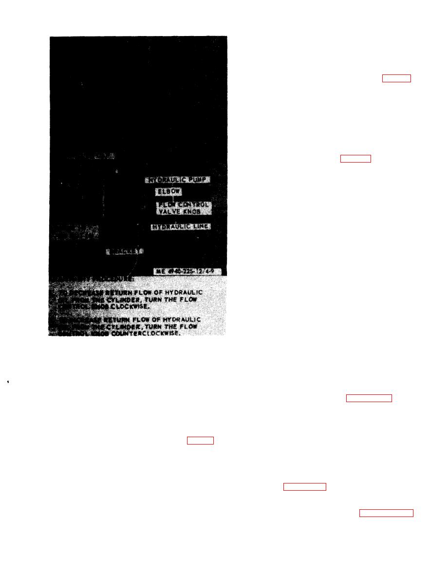
(1) Install the flow control valve in the elbow
and install the elbow in the cylinder pump (fig. 4-
9).
(2) Install the hydraulic pump in the bracket.
and secure with screws, nuts, and washers. Connect
line to flow control valve.
e. Bleeding Side Lifting Hydraulic System.
NOTE
See that all leaks are corrected before bleeding the
side lifting hydraulic system.
(1) Remove the filler cap (fig. 4-9) from the
top of the pump and add fluid as necessary in
accordance with the LO 5-4940-225-12. Install and
tighten filler cap.
(2) Pressurize the system and raise the side.
When the cylinder assembly reaches one-third its
extended position, any air in the system can be bled
by loosening the hydraulic line connection, at the
flow control valve, just enough that air in the line
can escape. When hydraulic fluid begins to appear,
tighten the connection. Refill the hydraulic pump
after bleeding and while side door is closed.
4-27. Side Lifting Cylinders and Hydraulic
Lines
a. General. A side lifting cylinder is located on
each side of the shop set body. The upper end of
each cylinder is attached to a rib in its respective
side door, The lower end of each is connected to a
removable bracket secured to the shop set floor.
Hydraulic oil flows into and out of the cylinders
through a flexible line connected at the bottom of
each cylinder.
b. Removal.
(1) Raise the side door on which the side lifting
cylinder is to be removed and secure in the raised
a. General. The side lifting hydraulic pumps are
position.
mounted on the front of the shop set body; one on
(2) Remove the side lifting cylinder and
each side. Each pump is manually operated by a
hydraulic lines as illustrated in figure 4-10.
handle stored on the front of the body adjacent to
c. Cleaning, Inspection, and Repair.
each pump. The pumps are secured to permanent
(1) Clean all parts with cleaning solvent and
mounting brackets welded to the shop set body.
dry thoroughly.
b. Removal.
(2) Inspect all parts for cracks, breaks, wear,
and other defects.
from the flow control valve.
(3) Replace a defective side lifting cylinder or
(2) Remove four screws, nuts and washers,
related parts and lines that cannot be repaired.
and remove the hydraulic pump from the bracket.
d. Installation.
(3) Remove the flow control valve from the
(1) Install the side lifting cylinder and lines as
elbow and remove the elbow from the hydraulic
illustrated in figure 4-10.
pump.
(2) Lower the side door.
c. Cleaning and Inspection.
(3) Bleed the side lifting cylinder and lifting
( 1 ) Clean external surface of the pump with a
door hydraulic system as described in paragraph 4-
cloth dampened in cleaning solvent and wipe dry.
22.
