TM 55-4920-402-13&P
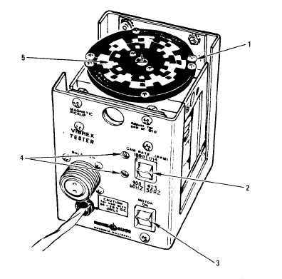
Figure 2-3. Tester Controls and Indicators
2-3. Rotor Vibration. The purpose of balancing and track-
ing a rotor is to reduce the vibration induced by the out-of-
balance rotor. In general, main rotor vibrations are in a
frequency range of 3 to 8 Hz and, because of this low vi-
bration rate and fairly low forces, are not terribly damaging
to the airframe. However, due to the low frequency range,
this type vibration causes great discomfort to the aircrew.
In contrast, tail rotor vibrations are much fester; i.e., 20 to
60 Hz. This frequency range causes relatively little dis-
comfort to the aircrew but results in greater darnage to the
airframe. This is evident in terms of skin cracks, loose
rivets, worn bearings and rod ends, pitch case bearings,
etc. Vibration can generally be reduced to four sources:
a. One-per-revolution lateral vibration in the plane of
the rotor disc is induced by improper weight distribution
around the center of rotation. This is correctable by adding
or subtracting weights at specific locations, orb y sweeping
the blades.
b. One-per-revolution vibration perpendicular to the
plane of the main rotor disc is induced by a faulty track
condition and is corrected by pitch link and/or tab adjust-
ment.
c. Multiples of one-per-revolution vibrations are general-
ly induced by aerodynamic forces, but are not correctable
by track or weight changes.
d. Vibratory forces are caused by shafts and accessories
which are out -of-balance or out of alignment.
2-4. Tuning the Balancer.The following paragraphs des-
cribe the use of the VIBREX in performing actual vibra-
tion measurements. Figure 2-4 illustrates the relationship
of the Balancer to airframe mounted components.
a. The heart of the Balancer is its tuneable electronic
band-pass filter. The Accelerometer generates an electrical
signal which is representative of all the mechanical motion
(vibration) of the point to which it is attached. To derive
a useful signal, all of the signal except that from the one-
per-revolution of the rotor being worked, must be rejected.
When properly tuned, the filter passes only the signal at
the RPM indicated by the Balancer’s RPM RANGE switch
and RPM TUNE dial, and rejects all other vibration fre-
quency rates.
b. In use, the Balancer is tuned by adjusting the RPM
TUNE dial until there is no change observed in clock angle
(Phazor or Strobex) whether the VERIFY TUNE button
is pushed or released. Pushing the VERIFY TUNE but-
ton switches the filter to its narrow mode, from stagger-
tuned, or board, with button released. If the filter is not
properly tuned, a difference in phase shift through the
filter, from normal to stagger-tuned will be seen as a
sharp change in clock angle, either in the ring-of-lights,
2-4
Change 3